Iranian Classification Society Rules

< Previous | Contents | Next >
CHAPTER 3 HULL SURVEYS OF SHIPS SUBJECT TO THE ENHANCED SURVEY PROGRAMME
Section 1 General
101. Application
1. In addition to the requirements specified in Ch 2, these requirements apply to hull surveys of ships
subject to the enhanced survey programme such as
tankers, etc.
2. Procedural requirements for certain ESP surveys
The objective of these requirements are to improve eration, the size of vessels and scope of surveys for
bulk carriers, oil tankers and chemical
the quality of surveys. Taking into consid- vessels noted below, it is more effective to
have more than one Surveyor examine the required spaces, holds or tanks and to provide mutual
support and consultation during the surveys in recommending repairs and actions required for con- ditions of class/recommendations.
(1) On ships 20,000 DWT and above, subject to ESP, starting with Special Survey No. 3, all spe- cial and intermediate hull classification surveys are to be carried out by at least two exclusive Surveyors. On bulk carriers 100,000 DWT and above of single side skin construction the inter- mediate hull classification survey between 10 and 15 years of age is to be performed by two exclusive Surveyors.
(2) This requires that at least two exclusive Surveyors attend on board at the same time to perform
the required survey. Where compatible with relevant laws and regulations, on dual class vessels, the requirement for two Surveyors may be fulfilled by having one Surveyor attend from each Society.
(3) Though each attending Surveyor is not required to perform all aspects of the required survey, they are required to consult with each other and to do joint Overall and Close-up Surveys to the extent necessary to determine the condition of the vessel. The extent of these surveys
should be sufficient for the Surveyors to agree on actions required to complete the survey with respect to renewals, repairs, and other recommendations or conditions of class. Each Surveyor is required to co-sign the survey report or indicate their concurrence in an equivalent manner.
(4) The following surveys may be witnessed by a single Surveyor;
- Thickness measurements in accordance with Ch 2, 109. of the Rules
- Tank testing in accordance with the applicable Ch 3 of the Rules
- Repairs carried out in association with intermediate and special hull classification survey, the extent of which have been agreed upon by the required two Surveyors during the
course of the surveys
(5) Surveyors used to fulfill this requirements are to be qualified in the survey processes involved.
(6) The onboard attendance of the Surveyors is to be documented according to the separate require-
ments specified by the Society.
Pt 1 Classification and Surveys
Ch 3 Hull Surveys of Ships Subject to the Enhanced Survey Programme Pt 1, Ch 3
![]()
102. Preparations for survey
1. Survey programme
(1) The Owner in cooperation with the Society is to work out a specific survey programme prior to the commencement of any part of:
- the Special Survey
- the Intermediate Survey for ships subject to the enhanced survey programme over 10 years of
age.
The survey programme is to be in a written format, based on the information in Annex 1-3, Table 1 of the Guidance. The survey is not to commence until the survey programme has been
agreed.
The survey programme at Intermediate Survey may consist of the survey programme at the pre- vious Special Survey supplemented by the executive hull summary of that Special Survey and
later relevant survey reports. The survey programme is to be worked out taking into account any amendments to the survey requirements implemented after the last Special Survey carried
out.
Prior to the development of the survey programme, the survey planning
questionnaire is to be
completed by the Owner based on the information set out in Annex 1-3, Table 2 of the Guidance, and forwarded to the Society.
(2) In developing the survey programme, the following documentation is to
be collected and con-
sulted with a view to selecting cargo holds/tanks, tanks, areas, and structural elements to be ex- amined:
(A) Bulk carriers and double skin bulk carriers
(B)
(a)
(b)
(c)
(d)
(e)
(f)
(g) Oil (a)
(b)
(c)
(d)
(e)
(f)
(g)
(h)
(i)
(j)
(k)
(l)
Survey status and basic ship information
Documentation on-board, as described in 103. 2 and 3
Main structural plans(scantling drawings), including information regarding use of high tensile steels(HTS)
Relevant previous survey and inspection reports from both the Society and the Owner
Information regarding the use of the ship's holds and tanks, typical cargoes and other relevant data
Information regarding corrosion prevention level on the new building
Information regarding the relevant maintenance level during operation tankers, chemical tankers and double hull oil tankers
Survey status and basic ship information
Documentation on-board, as described in 103. 2 and 3
Main structural plans of cargo and ballast tanks(scantling drawings), including in- formation regarding use of high tensile steels(HTS), clad steel and stainless steel(for
chemical tankers) Executive hull summary
Relevant previous damage and repair history
Relevant previous survey and inspection reports from both the Society and the Owner For oil tankers and double hull oil tankers cargo and ballast history for the last 3 years, including carriage of cargo under heated conditions, for chemical tankers information re-
garding the use of the ship's tanks, typical cargoes and other relevant data Details of the inert gas plant and tank cleaning procedures
Information and other relevant data regarding conversion or modification of the ship's
cargo and ballast tanks since the time of construction
Description and history of the coating and corrosion prevention system, if any Inspections by the Owner’s personnel during the last 3 years with reference to structural
deterioration in general, leakages in tank boundaries and piping and condition of the
coating and corrosion prevention system, if any
Information regarding the relevant maintenance level during operation including port state
control reports of inspection containing hull related deficiencies, Safety Management System non-conformities relating to hull maintenance, including the associated corrective action(s)
(m) Any other information that will help identify suspect areas and critical structural areas
Pt 1 Classification and Surveys
Ch 3 Hull Surveys of Ships Subject to the Enhanced Survey Programme Pt 1, Ch 3
![]()
(3) The submitted survey programme is to include relevant information including at least:
(A) Bulk carriers and double skin bulk carriers
(B)
(a)
(b)
(c)
(d)
(e)
(f)
(g)
(h)
(i)
(j)
(k)
Oil (a)
(b)
(c)
(d)
(e)
(f)
(g)
(h)
(i)
(j)
(k)
(l)
Basic ship information and particulars
Main structural plans(scantling drawings), including information regarding use of high tensile steels(HTS)
Plan of tanks and holds
List of tanks and holds with information on use, protection and condition of coating Conditions for survey(e.g., information regarding hold and tank cleaning, gas freeing, ventilation, lighting, etc.)
Provisions and methods for access to structures Equipment for surveys
Nomination of hold and tanks and areas for Close-up Survey
Nominations of sections and areas for thickness measurement Nomination of tanks for tank pressure testing
Damage experience related to the ship in question
tankers, chemical tankers and double hull oil tankers Basic ship information and particulars
Main structural plans of cargo and ballast tanks(scantling drawings), including in-
formation regarding use of high tensile steels(HTS), clad steel and stainless steel(for chemical tankers)
Arrangement of tanks
List of tanks with information on their use, extent and condition of coatings and corro- sion prevention systems
Conditions for survey(e.g., information regarding tank cleaning, gas freeing, ventilation,
lighting, etc.)
Provisions and methods for access to structures Equipment for surveys
Nomination of tanks and areas for Close-up Survey Nomination of areas and sections for thickness measurement
Nomination of tanks for tank pressure testing and the pipes that are to undergo pipe
pressure testing as per 404. 6 (for chemical tankers) Identification of the thickness measurement company
Damage experience related to the ship in question
(m) Critical structural areas and suspect areas, where relevant
(4) The Society will advise the Owner of the maximum acceptable structural corrosion diminution levels applicable to the vessel.
(5) Use may also be made of the process contained in Annex 1-3, Par 1 of the Guidance in con- junction with the preparation of the required survey programme. This process is a recommended
tool which may be invoked at the discretion
![]()
![]()
appropriate. See Guidance
of the Society, when considered necessary and
Pt 1 Classification and Surveys
Ch 3 Hull Surveys of Ships Subject to the Enhanced Survey Programme Pt 1, Ch 3
![]()
2. Conditions for survey
(1) The Owner is to provide the necessary facilities for a safe execution of the survey.
(A) In order to enable the attending Surveyors to carry out the survey, provisions for proper and safe access are to be agreed between the Owner and the Society and are to be in accord-
ance with IACS PR No.37(Procedural Requirement for Confined Space Safe Entry).
(B) Details of the means of access are to be provided in the survey planning questionnaire.
(C) In cases where the provisions of safety and required access are judged by the attending
Surveyor(s) not to be adequate, the survey of the spaces involved is not to proceed.
(2) Cargo holds, tanks and spaces are to be safe for access. Cargo holds, tanks and spaces are to be gas free and properly ventilated. Prior to entering a tank, void or enclosed space, it is to be
verified that the atmosphere in that space is free from hazardous gas and contains sufficient
oxygen.
(3) In preparation for survey and thickness measurements and to allow for a thorough examination,
all spaces are to be cleaned including removal from surfaces of all loose accumulated corrosion scale. Spaces are to be sufficiently clean and free from water, scale, dirt, oil residues etc. to re- veal corrosion, deformation, fractures, damages, or other structural deterioration as well as the
condition of the coating. However, those areas of structure whose renewal has already been de- cided by the Owner need only be cleaned and descaled to the extent necessary to determine the limits of the areas to be renewed.
(4) Sufficient illumination is to be provided to reveal corrosion, deformation, fractures, damages or other structural deterioration as well as the condition of the coating.
(5) Where soft or semi-hard coatings have been applied, safe access is to be provided for the
Surveyor to verify the effectiveness of the coating and to carry out an assessment of the con- ditions of internal structures which may include spot removal of the coating. When safe access cannot be provided, the soft or semi-hard coating is to be removed.
3. Access to structures
(1) For Overall Survey, means are to be provided to enable the Surveyor to examine the hull struc- ture in a safe and practical way.
(2) For Close-up Survey(for bulk carriers(except double skin bulk carriers), Close-up Survey of
hull structure, other than cargo hold shell frames), one or more of the following means for cess, acceptable to Surveyor, is to be provided:
(A) permanent staging and passages through structures
(B) temporary staging and passages through structures
the ac-
(C) hydraulic arm vehicles such
(D) boats or rafts
(E) portable ladders
(F) other equivalent means
as conventional cherry pickers, lifts and movable platforms
Pt 1 Classification and Surveys
Ch 3 Hull Surveys of Ships Subject to the Enhanced Survey Programme Pt 1, Ch 3
![]()
(3) For Close-up Surveys of the cargo hold shell frames of bulk carriers(except double skin bulk carriers) less than 100,000 DWT, one or more of the following means for access, acceptable to the Surveyor, is to be provided:
(A) permanent staging and passage through structures
(B) temporary staging and passage through structures
(C) portable ladder restricted to not more than 5 m in length may be accepted for surveys of lower section of a shell frame including bracket
(D) hydraulic arm vehicles such as conventional cherry pickers, lifts and movable platforms
(E) boats or rafts provided the structural capacity of the hold is sufficient to withstand static
loads at all levels of water
(F) other equivalent means
(4) For Close-up Surveys of the cargo hold shell frames of bulk carriers(except double skin bulk
carriers) 100,000 DWT and above, the use of portable ladders is not accepted, and one or more of the following means for access, acceptable to the Surveyor, is to be provided:
(A) Annual Surveys, Intermediate Survey under 10 years of age and Special Survey No. 1
(a)
(b)
(c)
(d)
(e)
permanent staging and passage through structures temporary staging and passage through structures
hydraulic arm vehicles such as conventional cherry pickers, lifts and movable platforms
boats or rafts provided the structural capacity of the hold is sufficient to withstand static loads at all levels of water
other equivalent means
(B) Subsequent Intermediate Surveys and Special Surveys
(a) either permanent or temporary staging and passage through structures for Close-up Survey of at least the upper part of hold frames
(b)
(c)
(d)
(e)
hydraulic arm vehicles such as conventional cherry pickers for surveys of lower and middle part of shell frames as alternative to staging
lifts and movable platforms
boats or rafts provided the structural capacity of the hold is sufficient to withstand static loads at all levels of water
other equivalent means
Notwithstanding the above requirements, the use of a portable ladder fitted with a mechanical device to secure the upper end of the ladder is acceptable for the "close-up examination of suf-
![]()
ficient extent, minimum 25 % of frames, to establish the condition of the lower region of the shell frames including approx. lower one third length of side frame at side shell and side frame end attachment and the adjacent shell plating of the forward cargo hold" at Annual Survey, re-
quired in 202. 4(10 years < age 15 years, Close-up Survey), and the "one other selected cargo hold" required in 202. 4(15 years age, Close-up Survey).
4. Equipment for survey
(1) Thickness measurement is normally to be carried out by means of ultrasonic test equipment.
The accuracy of the equipment is to be proven to the Surveyor as required.
![]()
![]()
(2) One or more of the following fracture detection procedures may be required if deemed neces- sary by the Surveyor: See Guidance
(A) radiographic equipment
(B) ultrasonic equipment
(C) magnetic particle equipment
(D) dye penetrant
(3) Explosimeter, oxygen-meter, breathing apparatus, lifelines, riding belts with rope and hook and whistles together with instructions and guidance on their use are to be made available during
the survey. A safety check-list is to be provided.
(4) Adequate and safe lighting is to be provided for the safe and efficient conduct of the survey.
(5) Adequate protective clothing is to be made available and used during the survey(e.g. safety hel- met, gloves, safety shoes, etc.).
5. Rescue and emergency response equipment
If breathing apparatus and/or other equipment is used as 'Rescue and emergency response equi- pment' then it is recommended that the equipment should be suitable for the configuration of the space being surveyed.
Pt 1 Classification and Surveys
Ch 3 Hull Surveys of Ships Subject to the Enhanced Survey Programme Pt 1, Ch 3
![]()
6. Survey at sea or at anchorage
(1) Survey at sea or at anchorage may be accepted provided the Surveyor is given the necessary assistance from the personnel onboard. Necessary precautions and procedures for carrying out the survey are to be in accordance with Par 1, Par 2, Par 3 and Par 4 above.
(2) A communication system is to be arranged between the survey party in the tank or space under examination and the responsible officer on deck. This system is to also include the personnel in
charge of ballast pump handling if boats or rafts are used.
(3) Surveys of tanks or applicable holds by means of boats or rafts may only be undertaken with
the agreement of the Surveyor, who is to take into account the safety arrangements provided,
including weather forecasting and ship response under foreseeable conditions and provided the
expected rise of water within the tank or hold does not exceed 0.25 m .
(4) When rafts or boats are used for Close-up Survey the following conditions are to be observed.
(A) only rough duty, inflatable rafts or boats, having satisfactory residual buoyancy and stability
even if one chamber is ruptured, are to be used.
(B) the boat or raft is to be tethered to the access ladder and an additional person is to be sta-
tioned down the access ladder with a clear view of the boat or raft.
(C) appropriate lifejackets are to be available for all participants.
(D) the surface of water in the tank or hold is to be calm(under all foreseeable conditions the ex-
pected rise of water within the tank or hold is not to exceed 0.25 m ) and the water level
stationary. On no account is to the level of the water be rising while the boat or raft is in use.
(E) the tank, hold or space must contain clean ballast water only. Even a thin sheen of oil or
cargo on the water is not acceptable.
(F) at no time is the water level to be allowed to be within 1 m of the deepest under deck web
face flat so that the survey team is not isolated from a direct escape route to the tank hatch.
Filling to levels above the deck transverses is only to be contemplated if a deck access man-
hole is fitted and open in the bay being examined, so that an escape route for the survey par-
ty is available at all times. Other effective means of escape to the deck may be considered.
(G) if the tanks(or spaces) are connected by a common venting system, or inert gas system, the
tank in which the boat or raft is to be used is to be isolated to prevent a transfer of gas from other tanks(or spaces).
(5) Rafts or boats alone may be allowed for inspection of the under deck areas for tanks or spaces, if the depth of the webs is 1.5 m or less.
(6) If the depth of the webs is more than 1.5 m , rafts or boats alone may be allowed only:
(A) when the coating of the under deck structure is in GOOD condition and there is no evi-
dence of wastage; or
(B) if a permanent means of access is provided in each bay to allow safe entry and exit. This means:
(a) access direct from the deck via a vertical ladder and a small platform fitted
imately 2 m below the deck in each bay; or
(b) access to deck from a longitudinal permanent platform having ladders to deck end of the tank. The platform shall, for the full length of the tank, be arranged
approx-
in each in level
with, or above, the maximum water level needed for rafting of under deck structure.
For this purpose, the ullage corresponding to the maximum water level is to be assumed not more than 3 m from the deck plate measured at the midspan of deck transverses
and in the middle length of the tank. (For oil tankers, chemical tankers and double hull oil tankers, see Fig 1.3.1)
If neither of the above conditions are met, then staging or an "other equivalent means" is to be provided for the survey of the under deck areas.
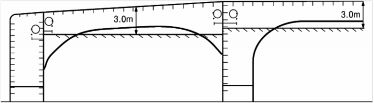
Fig 1.3.1
(7) The use of rafts or boats alone in (5) and (6) above does not preclude the use of boats or rafts to move about within a tank during a survey.
Pt 1 Classification and Surveys
Ch 3 Hull Surveys of Ships Subject to the Enhanced Survey Programme Pt 1, Ch 3
![]()
7. Survey planning meeting
(1) The establishment of proper preparation and close co-operation between the attending Surveyor(s) and the Owner’s representatives onboard prior to and during the survey are an essential part in the safe and efficient conduct of the survey. During the survey on board safety meetings are to be held regularly.
(2) Prior to the commencement of any part of the Special and Intermediate Survey, a survey plan- ning meeting is to be held between the attending Surveyor(s), the Owner's representative in at- tendance, the thickness measurement company operator(as applicable) and the master of the ship
or an appropriately qualified representative appointed by the master or company for the purpose to ascertain that all the arrangements envisaged in the survey programme are in place, so as to
![]()
![]()
ensure the safe and efficient conduct of the survey work to be carried out. See Guidance
(3) The following is an indicative list of items that are to be addressed in the meeting.
(A) schedule of the vessel(i.e. the voyage, docking and undocking manoeuvres, periods alongside,
cargo and ballast operations, etc.)
(B) provisions and arrangements for thickness measurements(i.e. access, cleaning/de-scaling, illu- mination, ventilation, personal safety)
(C) extent of the thickness measurements
(D) acceptance criteria
(E) extent of Close-up Survey and thickness measurement considering the coating condition and
suspect areas/areas of substantial corrosion
(F) execution of thickness measurements
(G) taking representative readings in general and where uneven corrosion/pitting is found
(H) mapping of areas of substantial corrosion
(I) communication between attending Surveyor(s) the thickness measurement company operator(s) and Owner representative(s) concerning findings
103. Documentation on board
1. General
(1) The Owner is to obtain, supply and maintain on board documentation as specified in Par 2 and
Par 3 below, which is to be readily available for the Surveyor.
(2) The documentation is to be kept on board for the life time of the ship.
2. Survey report file
(1) A survey report file is to be a part of the documentation on board consisting of
(A) Reports of structural surveys
(B) Executive hull summary
(C) Thickness measurement reports
(2) The survey report file is to be available also in the Owner's and the Society's management offices.
3. Supporting documents
The following additional documentation is to be available onboard.
(1) Main structural plans of cargo (holds) and ballast tanks (for vessels built under IACS Common Structural Rules(Pt 11, Pt 12 or Pt 13), these plans are to include for each structural element both the as-built and renewal thickness. Any thickness for voluntary addition is also to be clear- ly indicated on the plans. The midship section plan to be supplied on board the ship is to in- clude the minimum allowable hull girder sectional properties for hold/tank transverse section in all cargo holds/tanks)
(2) Previous repair history
(3) Cargo and ballast history
(4) Extent of use of inert gas plant and tank cleaning procedures
![]()
![]()
(5) The Owners inspection report with reference to See Guidance
(A) structural deterioration in general
(B) leakages in bulkheads and piping
(C) condition of corrosion prevention system, if any
(6) Any other information that will help identify critical ing inspection
(7) Survey programme as required in 102. 1 until such
Survey, as applicable, has been completed
structural areas and/or suspect areas requir-
time as the Special Survey or Intermediate
Pt 1 Classification and Surveys
Ch 3 Hull Surveys of Ships Subject to the Enhanced Survey Programme Pt 1, Ch 3
![]()
4. Review of documentation on board
Prior to survey, the Surveyor is to examine the completeness of the documentation onboard, and its contents as a basis for the survey.
![]()
![]()
104. Procedures for thickness measurements See Guidance
1. General
(1) The required thickness measurements, if not carried out by the Society itself, are to be wit- nessed by a Surveyor. The Surveyor is to be on board to the extent necessary to control the process. In this case, the control of thickness measurement process, review, verification and re- cord of attendance are to be in accordance with the separate requirements specified by the Society.
(2) The thickness measurement company is to be part of the survey planning meeting to be held prior to commencing the survey.
(3) Thickness measurements of structures in areas where Close-up Surveys are required shall ried out simultaneously with Close-up Surveys.
(4) In all cases the extent of the thickness measurements is to be sufficient as to represent
tual average condition.
(5) The thickness measurements are to be carried out by a qualified company certified Society.
2. Locations and number of measurements
(1) For vessels not built under IACS Common Structural Rules(Pt 11, Pt 12 or Pt 13),
be car-
the ac- by the
the re-
quirements for locations and number of thickness measurements are according to Annex 1-5, Table 3-1 of the Guidance and/or specific requirements, if exist, e.g. IACS UR S31(Renewal
Criteria for Side Shell Frames and Brackets in Single Side Skin Bulk Carriers and Single Side Skin OBO Carriers not Built in accordance with UR S12 Rev.1 or subsequent revisions).
(2) For vessels built under IACS Common Structural Rules(Pt 11, Pt 12 or Pt 13), the require- ments for locations and number of thickness measurements are according to followings.
(A) Considering the extent of thickness measurements according to the different structural ele- ments of the ship and survey(Special, Intermediate and Annual Survey), the locations of the
points to be measured are given for the most important items of the structure.
(B) Annex 1-5, Table 3-2 of the Guidance provides explanations and/or interpretations for the
application of those requirements indicated in the Rules,
thickness measurements related to the calculation of global measurements connected to Close-up Surveys.
(C) Figures in Annex 1-5, Table 3-2 of the Guidance are
which refer to both systematic hull girder strength and specific
provided to facilitate these ex-
planations and/or interpretations, and to show typical structural arrangements.
3. Reporting
(1) A thickness measurement report is to be prepared. The report is to give the location of meas- urements, the thickness measured as well as corresponding original thickness. Furthermore, the report is to give the date when the measurement was carried out, type of measuring equipment, names of personnel and their qualifications and has to be signed by the operator. The thickness measurement report is to follow the principles as specified in Annex 1-5 of the Guidance.
(2) The Surveyor is to review the final thickness measurements report and countersign the cover page.
Pt 1 Classification and Surveys
Ch 3 Hull Surveys of Ships Subject to the Enhanced Survey Programme Pt 1, Ch 3
![]()
105. Acceptance criteria for the corrosion
1. For vessels not built under IACS Common Structural Rules(Pt 11, Pt 12 or Pt 13), the acceptance criteria for the corrosion is according to Annex 1-5, Table 1 of the Guidance and/or specific re- quirements, if exist, e.g. IACS UR S31(Renewal Criteria for Side Shell Frames and Brackets in Single Side Skin Bulk Carriers and Single Side Skin OBO Carriers not Built in accordance with UR S12 Rev.1 or subsequent revisions).
2. For vessels built under IACS Common Structural Rules(Pt 11, Pt 12 or Pt 13), the acceptance criteria for the corrosion is according to Ch 13 of IACS Common Structural Rules for Bulk Carriers(Pt 11), Sec 12 of IACS Common Structural Rules for Double Hull Oil Tankers(Pt 12), Sub- part 1, Ch 13 of IACS Common Structural Rules for Bulk Carriers and Oil Tankers(Pt 13) and as specified in the followings.
(1) Acceptance criteria for pitting corrosion
(A) Side structures: for bulk carriers and double skin bulk carriers
If pitting
intensity in an area where coating is required, according to Ch 3, Sec 5 of IACS
Common
Structural Rules
for Bulk
Carriers(Pt 11) or Sub-part 1, Ch 3, Sec 4 of IACS
Common Structural Rules
for Bulk
Carriers and Oil Tankers(Pt 13), is higher than 15 %
(see Fig
1.2.1), thickness
measurements are to be performed to check the extent of pitting
(B)
corrosion. The 15 % is based on pitting or grooving on only one side of a plate.
In cases where pitting is exceeding 15 %, as defined above, an area of 300 mm or more, at the most pitted part of the plate, is to be cleaned to bare metal and the thickness is to be measured in way of the five deepest pits within the cleaned area. The least thickness meas-
ured in way of any of these pits is to be taken as the thickness to be recorded.
The minimum remaining thickness in pits, grooves or other local areas is to be greater than
![]()
the following without being greater than the renewal thickness( ):
- 75 % of the as-built thickness, in the frame and end brackets webs and flanges(only for
single skin bulk carriers)
- 70 % of the as-built thickness, in the side shell, hopper tank and topside tank plating at- tached to the each side frame, over a width up to 30 mm from each side of it.
Other structures
For plates with pitting intensity less than 20 % (see Fig 1.2.1), the measured thickness, ![]() of any individual measurement is to meet the lesser of the following criteria:
of any individual measurement is to meet the lesser of the following criteria:
![]()
![]() mm mm
mm mm
![]()
where,
as-built thickness of the member, in mm
![]()
voluntary thickness addition; thickness, in mm , voluntarily added as the Owner's extra margin for corrosion wastage in addition to ![]()
renewal thickness; minimum allowable thickness, in m m , below which renewal
of structural members is to be carried out.
![]()
total corrosion addition, in mm , defined in Ch 3, Sec 3 of IACS Common Structural Rules for Bulk Carriers(Pt 11), Sec 6 of IACS Common Structural Rules for Double Hull Oil Tankers(Pt 12) or Sub-part 1, Ch 3, Sec 3 of IACS Common Structural Rules for Bulk Carriers and Oil Tankers(Pt 13), as applicable.
![]()
measured thickness, in mm , on one items, i.e. average thickness on one item using the various measurements taken on this same item during periodical ship's in service surveys.
Pt 1 Classification and Surveys
Ch 3 Hull Surveys of Ships Subject to the Enhanced Survey Programme Pt 1, Ch 3
![]()
The average thickness across any cross section in the plating is not to be less than the re- newal criteria for general corrosion given in Ch 13 of IACS Common Structural Rules for Bulk Carriers(Pt 11), Sec 12 of IACS Common Structural Rules for Double Hull Oil Tankers(Pt 12) or Sub-part 1, Ch 13 of IACS Common Structural Rules for Bulk Carriers and Oil Tankers(Pt 13), as applicable.
(2) Acceptance criteria for edge corrosion
(A) Provided that the overall corroded height of the edge corrosion of the flange, or web in the case of flat bar stiffeners, is less than 25 % (see Fig 1.2.2), of the stiffener flange breadth
![]()
or web height, as applicable, the measured thickness, , is to meet the lesser of the fol- lowing criteria:
![]() mm
mm ![]() mm
mm
(B) The average measured thickness across the breadth or height of the stiffener is not to be less than the renewal criteria defined in Ch 13 of IACS Common Structural Rules for Bulk Carriers(Pt 11), Sec 12 of IACS Common Structural Rules for Double Hull Oil Tankers(Pt
12) or Sub-part 1, Ch 13 of IACS Common Structural Rules for Bulk Carriers and Oil Tankers(Pt 13), as applicable.
(C)
Plate edges at openings for manholes, lightening holes, etc. may be below the minimum
thickness given in Ch 13 IACS Common Structural Rules for Bulk Carriers(Pt 11), Sec 12 of IACS Common Structural Rules for Double Hull Oil Tankers(Pt 12) or Sub-part 1, Ch
13 of IACS Common Structural Rules for Bulk Carriers and Oil Tankers(Pt 13), as appli- cable, provided that:
(a) the maximum extent of the reduced plate thickness, below the minimum given in Ch 13 of IACS Common Structural Rules for Bulk Carriers(Pt 11), Sec 12 of IACS Common
Structural Rules for Double Hull Oil Tankers(Pt 12) or Sub-part 1, Ch 13 of IACS
Common Structural Rules for Bulk Carriers and Oil Tankers(Pt 13), as applicable, from the opening edge is not more than 20 % of the smallest dimension of the opening and does not exceed 100 mm .
(b) rough or uneven edges may be cropped-back provided that the maximum dimension of the opening is not increased by more than 10 % and the remaining thickness of the new
![]()
edge is not less than m m .
(3) Acceptance criteria for grooving corrosion
(A) Where the groove breadth is a maximum of 15 % of the web height, but not more than 30
![]()
mm (see Fig 1.2.3), the measured thickness, , in the grooved area is to meet the lesser of the following criteria:
![]() mm
mm ![]() mm
mm
but is not to be less than
![]()
mm
(B) Structural members with areas of grooving greater than those in (A) above are to be as- sessed based on the criteria for general corrosion as defined in Ch 13 of IACS Common Structural Rules for Bulk Carriers(Pt 11), Sec 12 of IACS Common Structural Rules for Double Hull Oil Tankers(Pt 12) or Sub-part 1, Ch 13 of IACS Common Structural Rules for Bulk Carriers and Oil Tankers(Pt 13), as applicable, using the average measured thick- ness across the plating/stiffener.
Pt 1 Classification and Surveys
Ch 3 Hull Surveys of Ships Subject to the Enhanced Survey Programme Pt 1, Ch 3
![]()
106. Reporting and evaluation of survey
1. Evaluation of survey report
(1) The data and information on the structural condition of the vessel collected during the survey is to be evaluated for acceptability and continued structural integrity of the vessel.
![]()
(2) In case of oil tankers(including double hull oil
length for freeboard( ) as defined in Pt 3, Ch
be evaluated by using the thickness of structural
tankers) of 130 m in length and upwards(i.e.
1, 103.), the ship's longitudinal strength is to members measured, renewed and reinforced, as
appropriate, during the Special Surveys carried out after the ship reached 10 years of age in ac-
cordance with the criteria for longitudinal strength of the ship's hull girder for oil tankers speci- fied in the separate requirements specified by the Society. However, the only thickness measure-
ment records which have been measured within one(1) year period from the date of the longi- tudinal strength evaluation shall be considered valid.
(3) For bulk carriers(including double skin bulk carriers) built under IACS Common Structural Rules for Bulk Carriers(Pt 11), the ship's longitudinal strength is to be evaluated by using the thick- ness of structural members measured, renewed and reinforced, as appropriate, during the Special Surveys carried out after the ship reaches 15 years of age (or during the Special Survey No. 3,
if this is carried out before the ship reaches 15 years) in accordance with the criteria for longi- tudinal strength of the ship's hull girder specified in Ch 13 of IACS Common Structural Rules
for Bulk Carriers(Pt 11). However, measured within one(1) year period be considered valid.
the only from the
thickness measurement records which have been date of the longitudinal strength evaluation shall
(4) Notwithstanding (2) and (3) above,
for ships built under IACS Common Structural Rules for
Bulk Carriers and Oil Tankers(Pt 13), the ship's longitudinal strength is to be evaluated by us-
ing the thickness of structural members measured, renewed and reinforced, as appropriate, during the Special Surveys carried out after the ship reached 10 years of age in accordance with the
criteria for longitudinal strength of the ship's hull girder specified in Sub-part 1, Ch 13 of IACS Common Structural Rules for Bulk Carriers and Oil Tankers(Pt 13). However, the only thick-
ness measurement records which have been measured within one(1) year period from the date of the longitudinal strength evaluation shall be considered valid.
(5) The final result of evaluation of the ship's longitudinal strength required (2) to (4) above, after renewal or reinforcement work of structural members, if carried out as a result of initial evalua-
tion, is to be reported as a part of the executive hull summary.
2. Reporting
An executive hull summary of the survey and results is to be issued to the Owner and placed on board the vessel for reference at future surveys. The executive hull summary is to be endorsed by the Society.
3. When a survey is split between different survey stations, a report is to be made for each portion of the survey. A list of items examined and/or tested(pressure testing, thickness measurements etc.) and an indication of whether the item has been credited, are to be made available to the next at- tending Surveyor(s), prior to continuing or completing the survey.
Pt 1 Classification and Surveys
Ch 3 Hull Surveys of Ships Subject to the Enhanced Survey Programme Pt 1, Ch 3
![]()
Section 2 Bulk Carriers
201. General
1. Application
(1) In addition to the requirements specified in Ch 2, the requirements apply to surveys of hull structure and piping systems in way of the following spaces for all bulk carriers with ESP nota- tion other than double skin bulk carriers as defined in 601. 2 (1).
(a) cargo holds, cofferdams, pipe tunnels, void spaces and fuel oil tanks within the cargo length area
(b) all ballast tanks
![]()
![]()
(2) The requirements contain the minimum extent of examination, thickness measurement and tank testing. The survey is to be extended when Substantial Corrosion and/or structural defects are found and include additional Close-Up Survey when necessary. See Guidance
(3) Ships, specified in Pt 7, Annex 7-5, 1 of the Guidance, which are required to comply with IACS UR S19(Evaluation of Scantlings of the Transverse Watertight Corrugated Bulkhead be- tween Cargo Holds Nos. 1 and 2, with Cargo Hold No.1 Flooded, for Existing Bulk Carriers) are subject to the additional thickness measurement guidance contained in Annex 1-5, Table 9 of the Guidance with respect to the vertically corrugated transverse watertight bulkhead between cargo hold Nos.1 and 2 for purpose of determining compliance with UR S19 prior to the rele- vant compliance deadline stipulated in UR S23(Implementation of IACS UR S19 and S22 for Existing Single Side Skin Bulk Carriers) as following and at subsequent Intermediate Surveys(for ships over 10 years of age) and Special Surveys for purpose of verifying continuing compliance with UR S19.
(A) For ships which were 20 years of age or more on 1 July 1998, by the due date of the first Intermediate or the due date of the first Special Survey to be held after 1 July 1998, whichever comes first, the compliance with the requirements specified in Pt 7, Annex 7-5 of the Guidance is to be confirmed.
(B) For ships which were 15 years of age or more but less than 20 years of age on 1 July 1998, by the due date of the first Special Survey to be held after 1 July 1998, but not lat- er than 1 July 2002, the compliance with the requirements specified in Pt 7, Annex 7-5 of the Guidance is to be confirmed.
(C) For ships which were 10 years of age or more but less than 15 years of age on 1 July 1998, by the due date of the first Intermediate, or the due date of the first Special Survey
to be held after the date on which the ship reaches 15 years of age but not later than the date on which the ship reaches 17 years of age, the compliance with the requirements 7-
specified in Pt 7, Annex
5 of the Guidance is to be confirmed.
(D) For ships which were 5 years of age or more but less than 10 years of age on 1 July 1998, by the due date, after 1 July 2003, of the first Intermediate or the first Special Survey after
the date on which the ship reaches 10 years of age, whichever occurs first, the compliance with the requirements specified in Pt 7, Annex 7-5 of the Guidance is to be confirmed.
(E) For ship which were less than 5 years of age on 1 July 1998, by the date on which the ship reaches 10 years of age, the compliance with the requirements specified in Pt 7,
Annex 7-5 of the Guidance is to be confirmed.
(F) Completion prior to 1 July 2003 of an Intermediate or Special Survey with a due date after
1 July 2003
2003 of an accepted.
cannot be used to postpone compliance. However, completion prior to 1 July Intermediate Survey the window for which straddles 1 July 2003 can be
Pt 1 Classification and Surveys
Ch 3 Hull Surveys of Ships Subject to the Enhanced Survey Programme Pt 1, Ch 3
![]()
(4) Ships, specified in Pt 7, Ch 3, Sec 17 which required to comply with IACS UR S31(Renewal Criteria for Side Shell Frames and Brackets in Single Side Skin Bulk Carriers and Single Side Skin OBO Carriers not Built in accordance with UR S12 Rev.1 or subsequent revisions) are subject to the additional thickness measurement guidance contained in Pt 7, Ch 3, Sec 17 and the separate requirements specified by the Society with respect to the side shell frames and brackets for the purpose of determining compliance with UR S31 prior to the relevant com- pliance deadline stipulated in UR S31 as following and at subsequent Intermediate and Special Surveys for purpose of verifying continuing compliance with UR S31.
(A) Bulk Carriers subject to the requirements specified in Pt 7, Ch 3, Sec 17 are to be as- sessed for compliance with the requirements of this rules and steel renewal, reinforcement or coating, where required in accordance with this rules, is to be carried out in accordance
with the following schedule and at subsequent Intermediate and Special Surveys.
(a) For bulk carriers which will be 15 years of age or more on 1 January 2004 by the due date of the first Intermediate or Special Survey after that date;
(b)
(c)
(d)
For bulk carriers which will be 10 years of age or more on 1 January 2004 by the due date of the first Special Survey after that date;
For bulk carriers which will be less than 10 years of age on 1 January 2004 by the date on which the ship reaches 10 years of age.
Completion prior to 1 January 2004 of an Intermediate or Special Survey with a due date after 1 January 2004 cannot be used to postpone compliance. However, completion
prior to 1 January 2004 of an Intermediate Survey the window for which straddles 1
January 2004 can be accepted.
(B) OBO carriers subject to the requirements specified in Pt 7, Ch 3, Sec 17 are to be as-
sessed for compliance with the requirements of this rules and steel renewal, reinforcement or
coating, where required in accordance with this rules, is to be carried out in accordance
with the following schedule and at subsequent Intermediate and Special Surveys.
(a)
(b)
(c)
For OBO carriers which will be 15 years of age or more on
date of the first Intermediate or Special Survey after that date;
For OBO carriers which will be 10 years of age or more on
date of the first Special Survey after that date;
For OBO carriers which will be less than 10 years of age on on which the ship reaches 10 years of age.
1 July 2005 by the due
1 July 2005 by the due
1 July 2005 by the date
(d) Completion prior to 1 July 2005 of an Intermediate or Special Survey with a due date after 1 July 2005 cannot be used to postpone compliance. However, completion prior to
1 July 2005 of an Intermediate Survey the window for which straddles 1 July 2005 can be accepted.
(5) For bulk carriers with hybrid cargo hold arrangements, e.g. with some cargo holds of single
side skin and others of double side skin, the requirements of Sec 6 are to apply to cargo hold of
double side skin and associated wing spaces.
(6) All bulk carriers, which required to comply with IACS UR S30(Cargo Hatch Cover
Securing Arrangements for Bulk Carriers not Built in accordance with UR S21(Rev.3)), not
built in ac- cordance with Pt 7, Ch 3, Sec 9 are to comply with the requirements specified
in Pt 7, Ch 3, Sec 18 in accordance with the following schedule:
(A) For ships which will be 15 years of age or more on 1 January 2004 by the due date of the first Intermediate or Special Survey after that date;
(B) For ships which will be 10 years of age or more on 1 January 2004 by the due date of the first Special Survey after that date;
(C) For ships which will be less than 10 years of age on 1 January 2004 by the date on which the ship reaches 10 years of age.
(D) Completion prior to 1 January 2004 of an Intermediate or Special Survey with a due date after 1 January 2004 cannot be used to postpone compliance. However, completion prior to
1 January 2004 of an Intermediate Survey the window for which straddles 1 January 2004 can be accepted.
Pt 1 Classification and Surveys
Ch 3 Hull Surveys of Ships Subject to the Enhanced Survey Programme Pt 1, Ch 3
![]()
2. Definitions
(1) A ballast tank is a tank which is used solely for salt water ballast, or, where applicable, a space which is used for both cargo and slat water ballast will be treated as a ballast tank when substantial corrosion has been found in that space.
(2) A transverse section includes all longitudinal members such as plating, longitudinals and gird-
ers at the deck, sides, bottom, inner bottom hopper sides, longitudinal bulkheads and bottom in top wing tanks. For transversely framed vessels, a transverse section includes adjacent frames
and their end connections in way of transverse sections.
(3) Spaces are separate compartments including holds, tanks, cofferdams and void spaces bounding cargo holds, decks and the outer hull.
Pt 1 Classification and Surveys
Ch 3 Hull Surveys of Ships Subject to the Enhanced Survey Programme Pt 1, Ch 3
![]()
202. Annual Survey
1. General
(1) The due range of Annual Survey is to be in accordance with the requirements of Ch 2, 201.
(2) The survey is to consist of an examination for the purpose of ensuring, as far as practicable, that the hull, weather decks, hatch covers, coamings and piping are maintained in a satisfactory condition.
2. Examination of the hull
(1) Examination of the hull plating and its closing appliances as far as can be seen.
(2) Examination of watertight penetrations as far as practicable.
3. Examination of weather decks, hatch covers and coamings
(1) Confirmation is to be obtained that no unapproved changes have been made to the hatch covers, hatch coamings and their securing and sealing devices since the last survey.
(2) A thorough survey of cargo hatch covers and coamings is only possible by examination in the open as well as closed positions and is to include verification of proper opening and closing
operation. As a result, the hatch cover sets within the forward 25 % of the ship’s length and at
least one additional set, such that all sets on the ship are assessed at least once in every 5-year period, are to be surveyed open, closed and in operation to the full extent on each direction at each Annual Survey, including:
(A) stowage and securing in open condition
(B) proper fit and efficiency of sealing in closed condition
(C) operational testing of hydraulic and power components, wires, chains, and link drives
The closing of the covers is to include the fastening of all peripheral and cross joint cleats or other securing devices. Particular attention is to be paid to the condition of the hatch covers in
the forward 25 % of the ship’s length, where sea loads are normally greatest.
(3) If there are indications of difficulty in operating and securing hatch covers, additional sets above those required by (2), at the discretion of the Surveyor, are to be tested in operation.
(4) Where the cargo hatch securing system does not function properly, repairs are to be carried out under the supervision of the Society.
(5) For each cargo hatch cover set, at each Annual Survey, the following items are to be surveyed:
(A) cover panels, including side plates, and stiffener attachments that may be accessible in the
open position by Close-up Survey(for corrosion, cracks, deformation)
(B) sealing arrangements of perimeter and cross joints(gaskets for condition and permanent de- formation, flexible seals on combination carriers, gasket lips, compression bars, drainage
channels and non return valves)
(C) clamping devices, retaining bars, cleating(for wastage, adjustment, and condition of rubber components)
(D) closed cover locating devices(for distortion and attachment)
(E) chain or rope pulleys
(F) guides
(G) guide rails and track wheels
(H) stoppers
(I) wires, chains, tensioners, and gypsies
(J) hydraulic system, electrical safety devices and interlocks
(K) end and interpanel hinges, pins and stools where fitted
(6) At each hatchway, at each Annual Survey, the coamings, with panel stiffeners and brackets are
to be checked for corrosion, cracks and deformation, especially of the coaming tops, including Close-up Survey.
(7) Where considered necessary, the effectiveness of sealing arrangements may be proved by hose
![]()
![]()
or chalk testing supplemented by dimensional measurements of seal compressing components.
See Guidance
Pt 1 Classification and Surveys
Ch 3 Hull Surveys of Ships Subject to the Enhanced Survey Programme Pt 1, Ch 3
![]()
(8) Where portable covers, wooden or steel pontoons are fitted, checking the satisfactory condition, where applicable, of:
(A) wooden covers and portable beams, carriers or sockets for the portable beam, and their curing devices
(B) steel pontoons, including Close-up Survey of hatch cover plating
(C) tarpaulins
(D) cleats, battens and wedges
(E) hatch securing bars and their securing devices
(F) loading pads/bars and the side plate edge
(G) guide plates and chocks
(H) compression bars, drainage channels and drain pipes(if any)
(9) Examination of flame screens on the open ends of air pipes to all bunker tanks.
(10) Examination of bunker and vent piping systems, including ventilators.
![]()
![]()
4. Examination of cargo holds See Guidance
![]()
![]()
![]()
![]()
![]()
![]()
![]()
The examination of cargo holds in Annual Survey is to be in accordance with the follows.
se-
10 years age 15 years2), 3) | 15 years age2), 3) | |
Overall Survey | All cargo holds | All cargo holds |
Close-up Survey | 1. Cargo Holds: - forward cargo hold 2. Extent: Close-up examination of sufficient extent, mini- mum 25% of frames, to establish the condition of the lower region of the shell frames includ- ing approx. lower one third length of side frame at side shell and side frame end attach- ment and the adjacent shell plating1) | 1. Cargo Holds: - forward cargo hold - one other selected cargo hold 2. Extent: Close-up examination of sufficient extent, mini- mum 25% of frames, to establish the condition of the lower region of the shell frames includ- ing approx. lower one third length of side frame at side shell and side frame end attach- ment and the adjacent shell plating1) |
Others | All piping and penetrations in cargo holds, includ- ing overboard piping, are to be examined. | All piping and penetrations in cargo holds, includ- ing overboard piping, are to be examined. |
(NOTES) 1) Where this level of survey reveals the need for remedial measures, the survey is to be extended to include a Close-up Survey of all of the shell frames and adjacent shell plating of that cargo hold as well as a Close-up Survey of sufficient extent of all remaining cargo holds. 2) When considered necessary by the Surveyor, or where extensive corrosion exists, thickness measurement is to be carried out. If the results of these thickness measurements indicate that substantial corrosion is found, the extent of thickness measurements is to be increased in accordance with the Guidance relating to the Rules. These increased thickness measurements are to be carried out before the Annual Survey is credited as completed. Suspect areas identified at previous surveys are to be examined. Areas of substantial corrosion identified at previous surveys are to have thickness measurement taken. For vessels built under the IACS Common Structural Rules(Pt 11 or Pt 13), the annual thickness gauging may be omitted where a hard pro- tective coating has been applied in accordance with the coating manufacturer's requirements and is maintained in GOOD condition. See Guidance 3) Where a hard protective coating in cargo holds is found to be in GOOD condition, the extent of Close-up Surveys and thickness measurements may be specially considered. | ||
Pt 1 Classification and Surveys
Ch 3 Hull Surveys of Ships Subject to the Enhanced Survey Programme Pt 1, Ch 3
![]()
5. Examination of ballast tanks
Examination of ballast tanks when required as a consequence of the results of the Special Survey and Intermediate Survey is to be carried out. When considered necessary by the Surveyor, or where extensive corrosion exists, thickness measurements are to be carried out. If the results of these
thickness ments is
measurements indicate that substantial corrosion is found, the extent of thickness to be increased in accordance with the Guidance relating to the Rules. These
measure- extended
thickness
measurements are to be carried out before the survey is credited as completed. Suspect
areas identified at previous surveys are to be examined. Areas of substantial corrosion identified at previous survey are to have thickness measurements taken. For vessels built under IACS Common
Structural Rules(Pt 11 or Pt 13), the annual thickness gauging may be omitted where a hard pro- tective coating has been applied in accordance with the coating manufacturer's requirements and is
![]()
![]()
maintained in GOOD condition. See Guidance
6. Additional Annual Survey requirements for the foremost cargo hold of ships subject to SOLAS XII/9.1
(1) Ships subject to SOLAS XII/9.1 are those meeting all the following conditions;
![]()
- Bulk Carriers of 150 m in length and upwards of single side skin construction,
- carrying solid bulk cargoes having a density of 1780 kg m and above,
- contracted for construction before 1 July 1999, and
- constructed with an insufficient number of transverse watertight bulkheads to enable them to
withstand flooding of the foremost cargo hold in all loading conditions and remain afloat in a satisfactory condition of equilibrium as specified in SOLAS XII/4.3.
![]()
![]()
(2) In accordance with SOLAS XII/9.1, for the foremost cargo hold of such ships, the additional survey requirements listed in the Guidance relating to the Rules shall apply. See Guidance
7. Additional Annual Survey requirements after determining compliance with SOLAS XII/12 and XII/13
(1) For ships complying with the requirements of SOLAS XII/12 for hold, ballast and dry space water level detectors, the Annual Survey is to include an examination and a test, at random, of the water ingress detection systems and of their alarms.
(2) For ships complying with the requirements of SOLAS XII/13 for the availability of pumping systems, the Annual Survey is to include an examination and a test of the means for draining
and pumping ballast tanks forward of the collision bulkhead and bilges of dry spaces any part
![]()
of which extends forward of the foremost cargo hold, and of their controls.
Pt 1 Classification and Surveys
Ch 3 Hull Surveys of Ships Subject to the Enhanced Survey Programme Pt 1, Ch 3
![]()
203. Intermediate Survey
1. General
(1) The due range of Intermediate Survey is to be in accordance with the requirements of Ch 2, 301.
(2) At each Intermediate Survey, in addition to the requirements of the Annual Survey, the follow- ing items are to be surveyed. Those items which are additional to the requirements of the Annual Survey may be surveyed either at or between the 2nd and 3rd Annual Survey.
(3) Bulk carriers exceeding 10 years of age up to 15 years of age, the following is to apply:
(a) The requirements of the Intermediate Survey are to be to the same extent to the previous
Special Survey as required in 204. and 102. 1. (Caution : In this case, the requirements specified in Ch 2, 403. are not need to be applied) However, internal examination of fuel tanks and pressure testing of all tanks are not required unless deemed necessary by the at-
![]()
![]()
tending Surveyor. See Guidance
(b)
In application of (a) above, the Intermediate Survey may be commenced at the second Annual Survey and be progressed during the succeeding year with a view to completion at
the third Annual Survey in lieu of the application of Ch 2, 401. 4 and 5.
(c) In application of (a) above, an under water survey may be considered in lieu of the require- ments of 204. 1 (6).
(4) Bulk carriers over 15 years of age, the following is to apply:
(a) The requirements of the Intermediate Survey are to be to the same extent to the previous
Special Survey as required in 204. and 102. 1. (Caution : In this case, the requirements specified in Ch 2, 403. are not need to be applied) However, internal examination of fuel
![]()
![]()
tanks and pressure testing of all tanks are not required unless deemed necessary by the at- tending Surveyor. See Guidance
(b)
In application of (a) above, the Intermediate Survey may be commenced at the second
Annual Survey and be progressed during the succeeding year with a view to completion at the third Annual Survey in lieu of the application of Ch 2, 401. 4 and 5.
(c) In application of (a) above, a survey in dry dock is to be part
of the Intermediate Survey.
The Overall and Close-up Surveys and thickness measurements, as applicable, of the lower
portions of the cargo holds and ballast tanks are to be carried
out in accordance with the
applicable requirements for Intermediate Surveys, if not already performed.
Note : Lower portions of the cargo holds and ballast tanks are considered to be the parts below light ballast water line.
2. Examination of ballast tanks
![]()
![]()
![]()
![]()
![]()
![]()
![]()
![]()
The examination of ballast tanks in Intermediate Survey is to be in accordance with the follows.
5 years age 10 years1), 2), 3) | 10 years age 15 years | 15 years age |
1. Overall Survey of representative ballast tanks 2. Overall Survey and Close-up Survey of suspect areas identified at previous surveys | 203. 1 (3) to be applied. | 203. 1 (4) to be applied. |
(NOTES) 1) The selection is to include fore and aft peak tanks and a number of other tanks, taking into account the to- tal number and type of ballast tanks. If such Overall Survey reveals no visible structural defects, the exami- nation may be limited to verification that the corrosion prevention system remains efficient. 2) Where POOR coating condition, corrosion or other defects are found in ballast tanks or where a hard pro- tective coating was not applied from the time of construction, the examination is to be extended to other ballast tanks of the same type. 3) In ballast tanks other than double bottom ballast tanks, where a hard protective coating is found in POOR condition, and it is not renewed, or where soft or semi-hard coating has been applied, or where a hard pro- tective coating was not applied from the time of construction, the tanks in question are to be examined and thickness measurements carried out as considered necessary at annual intervals. When such breakdown of hard protective coating is found in double bottom ballast tanks, of where a soft or semi-hard coating has been applied, or where a hard protective coating has not been applied, the tanks in question may be exam- ined at annual intervals. When considered necessary by the Surveyor, or where extensive corrosion exists, thickness measurements are to be carried out. See Guidance | ||
Pt 1 Classification and Surveys
Ch 3 Hull Surveys of Ships Subject to the Enhanced Survey Programme Pt 1, Ch 3
![]()
3. Examination of cargo holds
![]()
![]()
![]()
![]()
![]()
![]()
The examination of cargo holds in Intermediate Survey is to be in accordance with the follows.
5 years age 10 years1) | 10 years age 15 years | 15 years age | |
Overall Survey | All cargo holds | 203. 1 (3) to be applied. | 203. 1 (4) to be applied. |
Close-up Survey | 1. Cargo holds: - forward cargo hold - one other selected cargo hold. (extent : Survey of sufficient extent, minimum 25% of frames, is to be carried out to establish the condition of: shell frames including their upper and lower end attach- ments, adjacent shell plating, and transverse bulkheads) 2. Suspect areas found at previous surveys | 203. 1 (3) to be applied. | 203. 1 (4) to be applied. |
(NOTES) 1) Where considered necessary by the Surveyor as a result of the Overall and Close-up Survey, the survey is to be extended to include a Close-up Survey of all of the shell frames and adjacent shell plating of that cargo hold as well as a Close-up Survey of sufficient extent of all remaining cargo holds. See Guidance | |||
![]()
![]()
4. Extent of thickness measurement
(1) Bulk carriers exceeding 5 years of age up to 10 years of age, the following is to apply:
(a) Thickness measurements are to be carried out to an extent sufficient to determine both gen-
eral and local corrosion levels at areas subject to Close-up Survey, as described in Par 3.
The minimum requirement for thickness measurements at the Intermediate Survey are areas
found to be suspect areas at previous surveys.
(b) The thickness measurement may be specially considered provided the Surveyor is satisfied by the Close-up Survey, that there is no structural diminution and the hard protective coat- ings are found to be in a GOOD condition.
(c)
(d)
Where substantial corrosion is found, the extent of thickness measurements is to be in- creased in accordance with the Guidance relating to the Rules. These extended thickness measurements are to be carried out before the survey is credited as completed. Suspect areas
![]()
identified at previous surveys are to be examined. Areas of substantial corrosion identified at previous surveys are to have thickness measurements taken. For vessels built under IACS Common Structural Rules(Pt 11 or Pt 13), the identified substantial corrosion areas may be:
See Guidance![]()
(i) protected by a hard protective coating applied in accordance with the coating manu- facturer's requirements and examined at annual intervals to confirm the coating in way is still in GOOD condition, or alternatively
(ii) required to be measured at annual intervals.
Where the hard protective coating in cargo holds is found to be in GOOD condition, the
extent of Close-up Surveys and thickness measurements may be specially considered.
Note : For existing bulk carriers, where Owners may elect to coat or recoat cargo holds as not- ed above, consideration may be given to the extent of the Close-up Surveys and thick- ness measurement. Prior to the coating of cargo holds of existing ships, scantlings should be ascertained in the presence of a Surveyor.
(2) Bulk carriers exceeding 10 years of age up to 15 years of age, Par 1 (3) above is to apply.
(3) Bulk carriers exceeding 15 years of age, Par 1 (4) above is to apply.
![]()
(4) The side shell frames and brackets of cargo holds bounded by the single side shell of bulk car- riers which were not built in accordance with Pt 7, Ch 3, Sec 7 are to have thickness meas- urements taken for the extent of Close-up Survey according to the ship's age.
Pt 1 Classification and Surveys
Ch 3 Hull Surveys of Ships Subject to the Enhanced Survey Programme Pt 1, Ch 3
![]()
204. Special Survey
1. General
(1) The due range of Special Survey is to be in accordance with the requirements of Ch 2, 401.
(2) The Special Survey is to include, in addition to the requirements of the Annual Survey, exami- nation, tests, and checks of sufficient extent to ensure that the hull and related piping, as re- quired in (4), is in a satisfactory condition and is fit for its intended purpose for the new peri- od of class of 5 years to be assigned subject to proper maintenance and operation and to peri- odical surveys being carried out at the due dates.
(3) All cargo holds, ballast tanks, including double bottom tanks, pipe tunnels, cofferdams and void spaces bounding cargo holds, decks and outer hull are to be examined, and this examination is
to be supplemented by thickness measurement and testing as required in Par 5 and Par 6, to
ensure that the structural integrity remains effective. The aim of the examination is to discover
substantial corrosion, significant deformation, fractures, damages or other structural deterioration, that may be present.
(4) All piping systems within the spaces specified in (3) above are to be examined and operation-
ally tested to working pressure to attending Surveyor's satisfaction to ensure that tightness and condition remains satisfactory.
(5) The survey extent of ballast tanks converted to void spaces is to be specially considered in re-
lation to the requirements for ballast tanks.
(6) A survey in dry dock is to be a part of the Special Survey. The Overall and Close-up Surveys and thickness measurements, as applicable, of the lower portions of the cargo holds and ballast
tanks are to be carried out in accordance with the applicable requirements for Special Surveys,
if not already performed.
Note : Lower portions of the cargo holds and ballast tanks are considered to be the parts below
light ballast water line.
2. Tank protection
![]()
![]()
(1) Where provided, the condition of the corrosion prevention system of ballast tanks is to be examined. For ballast tanks, excluding double bottom ballast tanks, where a hard protective coat- ing is found in POOR condition and it is not renewed, where a soft or semi-hard coating has been applied, or where a hard protective coating has not been applied from the time of con- struction, the tanks in question are to be examined at annual intervals. Thickness measurements are to be carried out as deemed necessary by the Surveyor. See Guidance
(2) When such breakdown of hard protective coating is found in double bottom ballast tanks and it is not renewed, where a soft or semi-hard coating has been applied, or where a hard protective coating has not been applied from the time of construction, the tanks in question may be exam-
![]()
![]()
ined at annual intervals. When considered necessary by the Surveyor, or where extensive corro- sion exists, thickness measurements are to be carried out. See Guidance
(3) Where a hard protective coating is provided in cargo holds and is found in GOOD condition,
the extent of Close-up Surveys and thickness measurements may be specially considered.
3. Hatch covers and coamings
In addition to the requirements in 202. 3 of the Annual Survey, the following items are to be surveyed.
(1) Checking of the satisfactory operation of all mechanically operated hatch covers is to be made, including:
(a)
(b)
(c)
stowage and securing in open condition
proper fit and efficiency of sealing in closed condition
operational testing of hydraulic and power components, wires, chains, and link drives.
(2) Checking the effectiveness of sealing arrangements of all hatch covers by hose testing or equivalent.
![]()
(3) Thickness measurement of the hatch cover and coaming plating and stiffeners is to be carried out as given in Table 1.3.2.
Pt 1 Classification and Surveys
Ch 3 Hull Surveys of Ships Subject to the Enhanced Survey Programme Pt 1, Ch 3
![]()
4. Extent of Overall and Close-up Survey
(1) An Overall Survey of all tanks and spaces specified in 201. 1 (1) (a) and (b) is to be carried out at each Special Survey. Fuel oil tanks in cargo length area are to be surveyed as follows:
Special Survey No. 1 | Special Survey No. 2 | Special Survey No. 3 | Special Survey No. 4 and Subsequent |
- | One | Two | Half, minimum two |
(NOTES) 1. These requirements apply to tanks of integral (structural) type. 2. If a selection of tanks is accepted to be examined, then different tanks are to be examined at each Special Survey, on a rotational basis. 3. Peak tanks (all uses) are subject to internal examination at each Special Survey. 4. At Special Survey No. 3 and subsequent Special Surveys, one deep tank for fuel oil in the cargo area is to be included, if fitted. | |||
(2) The minimum requirements for Close-up Survey at Special Survey are given in Table 1.3.1.
(3) The Surveyor may
maintenance of the
extend spaces
the Close-up Survey as deemed necessary taking into account the under survey, the condition of the corrosion prevention system and
where spaces have
structural arrangements or details which have suffered defects in similar
spaces or on similar ships according to available information.
(4) For areas in spaces where hard protective coatings are found to be in a GOOD condition, the extent of Close-up Surveys according to Table 1.3.1 may be specially considered. (Refer also to 204. 2 (3))
5. Extent of thickness measurement
(1) The minimum requirements for thickness measurements at Special Survey are given in Table
1.3.2. For additional thickness measurement guidelines applicable to the vertically corrugated transverse watertight bulkhead between cargo hold Nos. 1 and 2 on ships subject to compliance with IACS URs S19 and S23, reference is to be made to 201. 1 (3) and Annex 1-5, Table 9 of the Guidance. For additional thickness measurement guidelines applicable to the side shell
frames and brackets on made to 201. 1 (4) and
fied by the Society.
(2) Provisions for extended
Guidance relating to the
ships subject to compliance with IACS UR S31, reference is to be
Pt 7, Ch 3, Sec 17 of the Rules and the separate requirements speci-
measurements for areas with substantial corrosion are given in the Rules and as may be additionally specified in the survey programme as
required in 102. 1. These extended thickness measurements are to be carried out before the sur-
![]()
![]()
vey is credited as completed. Suspect areas identified at previous surveys are to Areas of substantial corrosion identified at previous surveys are to have thickness taken. For vessels built under IACS Common Structural Rules(Pt 11 or Pt 13), substantial corrosion areas may be: See Guidance
(A) protected by a hard protective coating applied in accordance with the coating
be examined. measurements
the identified
manufacturer's
requirements and examined at annual intervals to confirm the GOOD condition, or alternatively
(B) required to be measured at annual intervals.
coating in way is still in
![]()
(3) The Surveyor may further extend the thickness measurements
Guidance
![]()
as deemed necessary. See
(4) For areas in tanks where hard protective coatings are found to extent of thickness measurement according to Table 1.3.2 may also to 204. 2 (3))
be in a GOOD condition, the be specially considered. (Refer
![]()
(5) Transverse sections are to be chosen where largest reductions are suspected to occur or are re- vealed from deck plating measurements, one of which is to be in the amidships area.
Pt 1 Classification and Surveys
Ch 3 Hull Surveys of Ships Subject to the Enhanced Survey Programme Pt 1, Ch 3
![]()
![]()
![]()
(6) Representative thickness measurement to determine both general and local levels of corrosion in the shell frames and their end attachments in all cargo holds and ballast tanks is to be carried out. Thickness measurement is also to be carried out to determine the corrosion levels on the transverse bulkhead plating. The extent of thickness measurements may be specially considered provided the Surveyor is satisfied by the Close-up Survey, that there is no structural diminution, and the hard protective coating where applied remains efficient. See Guidance
6. Extent of tank testing
The minimum requirements for tank testing at Special Survey are given in Table 1.3.3.
7. Additional Special Survey requirements after determining compliance with SOLAS XII/12 and XII/13
(1) For ships complying with the requirements of SOLAS XII/12 for hold, ballast and dry space water level detectors, the Special Survey is to include an examination and a test of the all wa- ter ingress detection systems and of their alarms.
(2) For ships complying with the requirements of SOLAS XII/13 for the availability of pumping systems, the Special Survey is to include an examination and a test of the means for draining
![]()
and pumping ballast tanks forward of the collision bulkhead and bilges of dry spaces any part of which extends forward of the foremost cargo hold, and of their controls.
Pt 1 Classification and Surveys
Ch 3 Hull Surveys of Ships Subject to the Enhanced Survey Programme Pt 1, Ch 3
![]()
![]()
![]()
Table 1.3.1 Minimum requirements for Close-up Survey at Special Survey of Bulk Carriers
Special Survey No. 1 | Special Survey No. 2 | Special Survey No. 3 | Special Survey No. 4 and Subsequent |
1. 25% of shell frames in the forward cargo hold at representative posi- tions, and selected frames in remaining cargo holds (*1) 2. One transverse web with associated plating and longitudinals in two representative ballast tanks of each type (i.e. topside, or hopper side tank) (*2) 3. Two selected cargo hold transverse bulkheads, in- cluding internal struc- ture of upper and lower stools, where fitted (*3) 4. All cargo hold hatch covers and coamings (plating and stiffeners) (*4) | 1. All shell frames in the forward cargo hold and 25% of shell frames in each of the remaining cargo holds including upper and lower end at- tachments and adjacent shell plating. For bulk carriers 100,000 DWT and above, all shell frames in the for- ward cargo hold and 50% of shell frames in each of the remaining cargo holds, including upper and lower end at- tachments and adjacent shell plating. (*1) 2. One transverse web with associated plating and longitudinals in each ballast tank (*2) 3. Forward and aft trans- verse bulkhead in one ballast tank, including stiffening system (*2) 4. All cargo hold trans- verse bulkheads, includ- ing internal structure of upper and lower stools, where fitted (*3) 5. All cargo hold hatch cov- ers and coamings (plating and stiffeners) (*4) 6. All deck plating and under deck structure in- side line of hatch open- ings between all cargo | 1. All shell frames in the forward and one other selected cargo hold and 50% of frames in each of the remaining cargo holds, including upper and lower end attach- ments and adjacent shell plating (*1) 2. All transverse webs with associated plating and longitudinals in each ballast tank (*2) 3. All transverse bulkheads in ballast tanks, includ- ing stiffening system (*2) 4. All cargo hold trans- verse bulkheads, includ- ing internal structure of upper and lower stools, where fitted (*3) 5. All cargo hold hatch covers and coamings (plating and stiffeners) (*4) 6. All deck plating and under deck structure in- side line of hatch open- ings between all cargo hold hatches. (*5) | 1. All shell frames in all cargo holds, including upper and lower end at- tachments and adjacent shell plating (*1) 2. All transverse webs with associated plating and longitudinals in each ballast tank (*2) 3. All transverse bulkheads in ballast tanks, includ- ing stiffening system (*2) 4. All cargo hold trans- verse bulkheads, includ- ing internal structure of upper and lower stools, where fitted (*3) 5. All cargo hold hatch covers and coamings (plating and stiffeners) (*4) 6. All deck plating and under deck structure in- side line of hatch open- ings between all cargo hold hatches. (*5) |
(NOTES) 1. (*1) to (*5) means as follows and are illustrated in Annex 1-6 of the Guidance: See Guidance (*1) : Cargo hold transverse frames (*2) : Transverse web frame or watertight transverse bulkhead in ballast tanks (*3) : Cargo hold transverse bulkheads stiffeners and girders (*4) : Cargo hold hatch covers and coamings (*5) : Deck plating and under deck structure inside line of hatch openings between cargo hold hatches 2. Close-up Survey of transverse bulkheads to be carried out at four levels: Level(a) : Immediately above the inner bottom and immediately above the line of gussets (if fitted) and shedders for ships without lower stool. Level(b) : Immediately above and below the lower stool shelf plate (for those ships fitted with lower stools), and immediately above the line of the shedder plates. Level(c) : About mid-height of the bulkhead. Level(d) : Immediately below the upper deck plating and immediately adjacent to the upper wing tank, and immediately below the upper stool shelf plate for those ships fitted with upper stools, or immedi- ately below the topside tanks. | |||
Pt 1 Classification and Surveys
Ch 3 Hull Surveys of Ships Subject to the Enhanced Survey Programme Pt 1, Ch 3
![]()
![]()
Table 1.3.2 Minimum requirements for thickness measurements at Special Survey of Bulk Carriers
Special Survey No. 1 | Special Survey No. 2 | Special Survey No. 3 | Special Survey No. 4 and Subsequent |
1. Suspect areas | 1. Suspect areas 2. Within the cargo length: 1) Two transverse sections of deck plating outside line of cargo hatch openings 3. 1) Wind and water strakes in way of the trans- verse sections consid- ered under 2 above 2) Selected wind and wa- ter strakes outside the cargo length area 4. Measurement, for general assessment and recording of corrosion pattern, of those structural members subject to Close-up Survey according to Table 1.3.1 5. See 201. 1 (4), Pt 7, Ch 3, Sec 17 and the sepa- rate requirements specified by the Society for addi- tional thickness measure- ment guidelines applicable to the side shell frames and brackets on ships sub- ject to compliance with IACS UR S31 | 1. Suspect areas 2. Within the cargo length: 1) Each deck plate outside line of cargo hatch openings 2) Two Transverse Sections, one in the amidship area, outside line of cargo hatch openings 3) All wind and water strakes 3. Selected wind and water strakes outside the cargo length area 4. Measurement, for general assessment and recording of corrosion pattern, of those structural members subject to Close-up Survey according to Table 1.3.1 5. See 201. 1 (3) and Annex 1-5, Table 9 of the Guidance for additional thickness measurement guidelines applicable to the vertically corrugated trans- verse watertight bulkhead between cargo hold Nos. 1 and 2 on ships subject to compliance with IACS URs S19 and S23 6. See 201. 1 (4), Pt 7, Ch 3, Sec 17 and the sepa- rate requirements specified by the Society for addi- tional thickness measure- ment guidelines applicable to the side shell frames and brackets on ships sub- ject to compliance with IACS UR S31 | 1. Suspect areas 2. Within the cargo length: 1) Each deck plate outside line of cargo hatch openings 2) Three Transverse Sections, one in the amidship area, outside line of cargo hatch openings 3) Each bottom plate 3. All wind and water strakes, full length 4. Measurement, for general assessment and recording of corrosion pattern, of those structural members subject to Close-up Survey according to Table 1.3.1 5. See 201. 1 (3) and Annex 1-5, Table 9 of the Guidance for additional thickness measurement guidelines applicable to the vertically corrugated trans- verse watertight bulkhead between cargo hold Nos. 1 and 2 on ships subject to compliance with IACS URs S19 and S23 6. See 201. 1 (4), Pt 7, Ch 3, Sec 17 and the sepa- rate requirements specified by the Society for addi- tional thickness measure- ment guidelines applicable to the side shell frames and brackets on ships sub- ject to compliance with IACS UR S31 |
Pt 1 Classification and Surveys
Ch 3 Hull Surveys of Ships Subject to the Enhanced Survey Programme Pt 1, Ch 3
![]()
![]()

![]()
![]()
Table 1.3.3 Minimum requirements for tank testing at Special Survey of Bulk Carriers
No. of Special Survey Tanks or spaces | Special Survey No. 1 | Special Survey No. 2 | Special Survey No. 3 | Special Survey No. 4 and Subsequent |
All boundaries of ballast tanks, deep tanks and cargo holds used for water ballast within the cargo length area |
|
|
|
|
(NOTES) 1. For fuel oil tanks within the cargo length area, only representative tanks are to be pressure tested. 2. The Surveyor may extend the tank testing as deemed necessary. See Guidance 3. Boundaries of ballast tanks are to be tested with a head of liquid to the top of air pipes. 4. Boundaries of ballast holds are to be tested with a head of liquid to near to the top of hatches. 5. Boundaries of fuel oil tanks are to be tested with a head of liquid to the highest point that liquid will rise under service conditions. Tank testing of fuel oil tanks may be specially considered based on a satisfactory external examination of the tank boundaries, and a confirmation from the Master stating that the pressure testing has been carried out according to the requirements with satisfactory results. 6. The testing of double bottom and other spaces not designed for the carriage of liquid may be omitted, pro- vided a satisfactory internal examination together with an examination of the tanktop is carried out. | ||||
Pt 1 Classification and Surveys
Ch 3 Hull Surveys of Ships Subject to the Enhanced Survey Programme Pt 1, Ch 3
![]()
Section 3 Oil Tankers
301. General
1. Application
(1) In addition to the requirements specified in Ch 2, the requirements apply to surveys of hull structure and piping systems in way of the following spaces for all oil tankers with ESP nota- tion other than Double Hull Oil Tankers as defined in 501. 2 (1).
(a) cargo tanks, pump rooms, cofferdams, pipe tunnels, void spaces within the cargo area
(b) all ballast tanks
(2) The requirements contain the minimum extent of examination, thickness measurements and tank
testing. The survey is to be extended when substantial corrosion and/or structural defects are
![]()
![]()
found and include additional Close-up Survey when necessary. See Guidance
2. Definitions
(1) A transverse section includes all longitudinal members such as plating, longitudinals and gird- ers at the deck, sides, bottom, inner bottom and longitudinal bulkheads. For transversely framed vessels, a transverse section includes adjacent frames and their end connections in way of trans- verse sections.
(2) Cargo area is that part of the ship which contains cargo tanks, slop tanks and cargo/ballast pump- rooms, cofferdams, ballast tanks and void spaces adjacent to cargo tanks and also deck areas
throughout the entire length and breadth of the part of the ship over the above mentioned
spaces.
(3) A ballast tank is a tank which is used solely for the
carriage of salt water ballast.
(4) A combined cargo/ballast tank is a tank which is
water as a routine part of the vessel's operation and
used for the carriage will be treated as a
of cargo or ballast
ballast tank. Cargo
tanks in which water ballast might be carried only in exceptional cases per MARPOL Annex I,
![]()
Ch 4, Reg. 18.3 are to be treated as cargo tanks.
Pt 1 Classification and Surveys
Ch 3 Hull Surveys of Ships Subject to the Enhanced Survey Programme Pt 1, Ch 3
![]()
302. Annual Survey
1. General
(1) The due range of Annual Survey is to be in accordance with the requirements of Ch 2, 201.
(2) The survey is to consist of an examination for the purpose of ensuring, as far as practicable, that the hull and piping are maintained in a satisfactory condition.
2. Examination of the hull
(1) Examination of the hull plating and its closing appliances as far as can be seen.
(2) Examination of watertight penetrations as far as practicable.
3. Examination of weather decks
(1) Examination of cargo tank openings including gaskets, covers, coamings and flame screens.
(2) Examination of cargo tanks pressure/vacuum valves and flame screens.
(3) Examination of flame screens on the open ends of air pipes to all bunker tanks.
(4) Examination of cargo, crude oil washing, bunker and vent piping systems, including vent masts
and headers.
4. Examination of cargo pump rooms and pipe tunnels(if fitted)
(1) Examination of all pump room bulkheads for signs of oil leakage or fractures and, in particular, the sealing arrangements of all penetrations of pump room bulkheads.
(2) Examination of the condition of all piping systems.
5. Examination of ballast tanks
Examination of ballast tanks where required as a consequence of the results of the Special Survey(See 304. 2) and Intermediate Survey(See 303. 3) is to be carried out. When considered necessary by the Surveyor, or when extensive corrosion exists, thickness measurements are to be carried out and if the results of these thickness measurements indicate that substantial corrosion is found, the extent of thickness measurements is to be increased in accordance with the Guidance re- lating to the Rules. These extended thickness measurements are to be carried out before the survey is credited as completed. Suspect areas identified at previous surveys are to be examined. Areas of
![]()
substantial corrosion
Guidance
![]()
identified at previous surveys are to have thickness measurements taken. See
Pt 1 Classification and Surveys
Ch 3 Hull Surveys of Ships Subject to the Enhanced Survey Programme Pt 1, Ch 3
![]()
303. Intermediate Survey
1. General
(1) The due range of Intermediate Survey is to be in accordance with the requirements of Ch 2, 301.
(2) At each Intermediate Survey, in addition to the requirements of the Annual Survey, the follow- ing items are to be surveyed. Those items which are additional to the requirements of the Annual Survey may be surveyed either at or between the 2nd and 3rd Annual Survey.
(3) Oil tankers exceeding 10 years of age up to 15 years of age, the following is to apply:
(a) The requirements of the Intermediate Survey are to be to the same extent as the previous
Special Survey as required in 102. 1 and 304. (Caution : In this case, the requirements specified in Ch 2, 403. are not need to be applied) However, pressure testing of cargo and ballast tanks and the requirements for longitudinal strength evaluation of hull girder as re-
![]()
![]()
quired in 105. 1 (2) are not required unless deemed necessary by the attending Surveyor.
See Guidance
(b)
(c)
(4) Oil
(a)
(b)
(c)
In application of (a) above, the Intermediate Survey may be commenced at the second Annual Survey and be progressed during the succeeding year with a view to completion at the third Annual Survey in lieu of the application of Ch 2, 401. 4 and 5.
In application of (a) above, an under water survey may be considered in lieu of the require- ments of 304. 1 (5).
tankers over 15 years of age, the following is to apply:
The requirements of the Intermediate Survey are to be to the same extent as the previous
Special Survey as required in 102. 1 and 304. (Caution : In this case, the requirements specified in Ch 2, 403. are not need to be applied) However, pressure testing of cargo and ballast tanks and the requirements for longitudinal strength evaluation of hull girder as re-
![]()
quired in 105. 1 (2) are not required unless deemed necessary by the attending Surveyor.
See Guidance![]()
In application of (a) above, the Intermediate Survey may be commenced at the second Annual Survey and be progressed during the succeeding year with a view to completion at the third Annual Survey in lieu of the application of Ch 2, 401. 4 and 5.
In application of (a) above, a survey in dry dock is to be a part of the Intermediate
Survey. The Overall and Close-up Surveys and thickness measurements, as applicable, of the lower portions of the cargo tanks and ballast tanks are to be carried out in accordance with the applicable requirements for Intermediate Surveys, if not already performed.
Note : Lower portions of the cargo and ballast tanks are considered to be the parts below light ballast water line.
2. For weather decks, an examination as far as applicable of:
(1) Cargo, crude oil washing, bunker, ballast, steam and vent piping systems as well as vent masts and headers is to be carried out.
(2) If upon examination there is any doubt as to the condition of the piping, the piping may be re- quired to be pressure tested, thickness measured or both.
3. Extent of examination
![]()
![]()
![]()
![]()
![]()
![]()
![]()
![]()
The examination in Intermediate Survey is to be in accordance with the follows.
5 years age 10 years1), 2) | 10 years age 15 years | 15 years age |
1. All ballast tanks 2. Suspect areas identified at previous surveys | 303. 1 (3) to be applied. | 303. 1 (4) to be applied. |
(NOTES) 1) When considered necessary by the Surveyor, thickness measurement and testing are to be carried out to en- sure that the structural integrity remains effective. See Guidance 2) A ballast tank is to be examined at subsequent annual intervals where: - a hard protective coating has not been applied from the time of construction, or - a soft or semi-hard coating has been applied, or - substantial corrosion is found within the tank, or - the hard protective coating is found to be in less than GOOD condition and the hard protective coating is not repaired to the satisfaction of the Surveyor. | ||
Pt 1 Classification and Surveys
Ch 3 Hull Surveys of Ships Subject to the Enhanced Survey Programme Pt 1, Ch 3
![]()
304. Special Survey
1. General
(1) The due range of Special Survey is to be in accordance with the requirements of Ch 2, 401.
(2) The Special Survey is to include, in addition to the requirements of the Annual Survey, exami- nation, tests and checks of sufficient extent to ensure that the hull and related piping, as re- quired in (4), is in a satisfactory condition and is fit for its intended purpose for the new peri- od of class of 5 years to be assigned, subject to proper maintenance and operation and to peri- odical surveys being carried out at the due dates.
(3) All cargo tanks, ballast tanks, including double bottom tanks, pump rooms, pipe tunnels, coffer- dams and void spaces bounding cargo tanks, decks and outer hull are to be examined, this ex-
amination is to be supplemented by thickness measurement and testing as required in Par 4 and
Par 5, to ensure that the structural integrity remains effective. The aim of the examination is to
discover substantial corrosion, significant deformation, fractures, damages or other structural dete- rioration, that may be present.
(4) Cargo piping on deck, including crude oil washing (COW) piping, cargo and ballast piping with-
in the tanks and
working pressure main satisfactory.
spaces specified in (3) above are to be examined and operationally tested to
to attending Surveyor's satisfaction to ensure that tightness and condition re- Special attention is to be given to any ballast piping in cargo tanks and cargo
(5)
![]()
![]()
piping in ballast tanks and void spaces, and Surveyors are to be advised on all occasions when this piping, including valves and fittings are opened during repair periods and can be examined internally. See Guidance
A survey in dry dock is to be a part of the Special Survey. The Overall and Close-up Surveys and thickness measurements, as applicable, of the lower portions of the cargo tanks and ballast tanks are to be carried out in accordance with the applicable requirements for Special Surveys, if not already performed.
Note : Lower portions of the cargo and ballast tanks are considered to be the parts below light ballast water line.
2. Tank protection
Where provided, the condition of the corrosion prevention system of cargo tanks is to be examined. A ballast tank is to be examined at subsequent annual intervals where:
- a hard protective coating has not been applied from the time of construction, or
- a soft or semi-hard coating has been applied, or
- substantial corrosion is found within the tank, or
![]()
- the hard protective coating is found to be in less than GOOD condition and the hard protective coating is not repaired to the satisfaction of the Surveyor.
![]()
Thickness measurements are to be carried out as deemed necessary by the Surveyor. See Guidance
3. Extent of Overall and Close-up Survey
(1) An Overall Survey of all tanks and spaces specified in 301. 1 (1) (a) and (b) is to be carried out at each Special Survey.
(2) The minimum requirements for Close-up Survey at Special Survey are given in Table 1.3.4.
(3) The Surveyor may extend the Close-up Survey as deemed necessary taking into account the
maintenance of the tanks under survey, the condition of the corrosion prevention system and al- so in the following cases:
(a) In particular, tanks having structural arrangements or details which have suffered defects in similar tanks or on similar ships according to available information.
(b) In tanks which have structures approved with sion control system.
(4) For areas in tanks where hard protective coatings
reduced scantlings due to an approved corro-
are found to be in GOOD condition, the ex-
![]()
tent of Close-up Surveys according to Table 1.3.4 may be specially considered.
Pt 1 Classification and Surveys
Ch 3 Hull Surveys of Ships Subject to the Enhanced Survey Programme Pt 1, Ch 3
![]()
4. Extent of thickness measurement
(1) The minimum requirements for thickness measurements at Special Survey are given in Table 1.3.5.
![]()
![]()
(2) Provisions for extended measurements for areas with substantial corrosion are given in the Guidance relating to the Rules, and as may be additionally specified in the survey programme as required in 102. 1. These extended thickness measurements are to be carried out before the survey is credited as completed. Suspect areas identified at previous surveys are to be examined. Areas of substantial corrosion identified at previous surveys are to have thickness measurements taken. See Guidance
![]()
(3) The Surveyor may further extend the thickness measurements as deemed necessary.
Guidance
![]()
See
(4) For areas in tanks where hard protective coatings are found to be in a GOOD condition, the extent of thickness measurements according to Table 1.3.5 may be specially considered.
(5) Transverse sections are to be chosen where the largest reductions are suspected to occur or are revealed from deck plating measurements.
![]()
(6) In case where two or three sections are to be measured, at least one is to include a ballast
![]()
![]()
tank within 0.5 amidships. In case of oil tankers of 130 m in length and upwards(i.e. length for freeboard( ) as defined in Pt 3, Ch 1, 103.) and more than 10 years of age, for the eval- uation of the ship's longitudinal strength as required in 106. 1 (2), the sampling method of thickness measurements is given in the Guidance relating to the Rules. See Guidance
5. Extent of tank testing
(1) The minimum requirements for tank testing at Special Survey are given in Table 1.3.6.
(2) Cargo tank testing carried out by the vessel's crew under the direction of the Master may be accepted by the Surveyor provided the following conditions are complied with:
(A) a tank testing procedure has been submitted by the Owner and reviewed by the Society pri-
or to the testing being carried out.
(B) there is no record of leakage, distortion or substantial corrosion that would affect the struc- tural integrity of the tank.
(C) the tank testing has been satisfactorily carried out within Special Survey window not more than 3 months prior to the date of the survey on which the Overall or Close-up Survey is
completed.
(D) the satisfactory results of the testing is recorded in the vessel's
(E) the internal and external condition of the tanks and associated structure are found sat- isfactory by the Surveyor at the time of the Overall and Close-up Survey.
Pt 1 Classification and Surveys
Ch 3 Hull Surveys of Ships Subject to the Enhanced Survey Programme Pt 1, Ch 3
![]()
![]()
![]()
![]()
![]()
![]()
Table 1.3.4 Minimum requirements for Close-up Survey at Special Survey of Oil Tankers, Ore/Oil Ships and etc.1) See Guidance
Special Survey No. 1 | Special Survey No. 2 | Special Survey No. 3 | Special Survey No. 4 and Subsequent |
1. One web frame ring in a ballast wing tank, if any, or a cargo wing tank, used primarily for water ballast (*1) 2. One deck transverse in a cargo oil tank (*2) 3. One transverse bulkhead in a ballast tank (*4) 4. One transverse bulkhead in a cargo oil wing tank (*4) 5. One transverse bulkhead in a cargo oil centre tank (*4) | 1. All web frame rings in a ballast wing tank, if any, or a cargo wing tank, used primarily for water ballast (*1) 2. One deck transverse in each of the remaining ballast tanks, if any (*2) 3. One deck transverse in a cargo wing tank (*2) 4. One deck transverse in two cargo centre tanks (*2) 5. Both transverse bulk- heads in a wing ballast tank, if any, or a cargo wing tank used primarily for water ballast (*3) 6. One transverse bulkhead in each remaining ballast tank (*4) 7. One transverse bulkhead in a cargo oil wing tank (*4) 8. One transverse bulkhead in two cargo centre tanks (*4) | 1. All web frame rings in all ballast tanks (*1) 2. All web frame rings in a cargo wing tank (*1) 3. A minimum of 30% of all web frame ring in each remaining cargo wing tank (*1)2) 4. All transverse bulkheads in all cargo and ballast tanks (*3) 5. A minimum of 30% of deck and bottom trans- verse including adjacent structural members in each cargo centre tank (*5) 6. As considered necessary by the Surveyor (*6) | 1. All web frames rings in all ballast tanks (*1) 2. All web frame rings in a cargo wing tank (*1) 3. A minimum of 30% of all web frame ring in each remaining cargo wing tank (*1)2) 4. All transverse bulkheads in all cargo and ballast tanks (*3) 5. A minimum of 30% of deck and bottom trans- verse including adjacent structural members in each cargo centre tank (*5) 6. As considered necessary by the Surveyor (*6) 7. Additional transverses included as deemed necessary by the Society |
(NOTES) 1) (*1) to (*6) mean as follows and are illustrated in Annex 1-6 of the Guidance: See Guidance (*1) : Complete transverse web frame ring including adjacent structural members (*2) : Deck transverse including adjacent deck structural members (*3) : Transverse bulkhead complete including girder system and adjacent structural members (*4) : Transverse bulkhead lower part including girder system and adjacent structural members (*5) : Deck and bottom transverse including adjacent structural members (*6) : Additional complete transverse web frame ring 2) The 30 % is to be rounded up to the next whole integer. | |||
Pt 1 Classification and Surveys
Ch 3 Hull Surveys of Ships Subject to the Enhanced Survey Programme Pt 1, Ch 3
![]()
Table 1.3.5 Minimum requirements for thickness Tankers, Ore/Oil Ships and etc.
measurements at Special Survey of Oil
Special Survey No. 1 | Special Survey No. 2 | Special Survey No. 3 | Special Survey No. 4 and Subsequent |
1. Suspect areas 2. One transverse section of deck plating for the full beam of the ship within the cargo area (in way of a ballast tank, if any, or a cargo tank used primarily for water ballast) 3. Measurements, for gen- eral assessment and re- cording of corrosion pattern, of those struc- tural members subject to Close-up Survey ac- cording to Table 1.3.4 | 1. Suspect areas 2. Within the cargo area: 1) Each deck plate 2) One transverse section 3. Measurements, for gen- eral assessment and re- cording of corrosion pattern, of those struc- tural members subject to Close-up Survey ac- cording to Table 1.3.4 4. Selected wind and wa- ter strakes outside the cargo area | 1. Suspect areas 2. Within the cargo area: 1) Each deck plate 2) Two transverse sections1) 3) All wind and water strakes 3. Measurements, for gen- eral assessment and re- cording of corrosion pattern, of those struc- tural members subject to Close-up Survey ac- cording to Table 1.3.4 4. Selected wind and wa- ter strakes outside the cargo area | 1. Suspect areas 2. Within the cargo area: 1) Each deck plate 2) Three transverse sections1) 3) Each bottom plate 3. Measurements, for gen- eral assessment and re- cording of corrosion pattern, of those struc- tural members subject to Close-up Survey ac- cording to Table 1.3.4 4. All wind and water strakes, full length |
(NOTES) 1) At least one section is to include a ballast tank within 0.5 | |||
![]()
![]()
![]()
Table 1.3.6 Minimum requirements for tank testing at and etc.
Special Survey of Oil Tankers, Ore/Oil Ships
Special Survey No. 1 | Special Survey No. 2 and Subsequent |
1. All ballast tank boundaries 2. Cargo tank boundaries facing ballast tanks, void spaces, pipe tunnels, pump-rooms or cofferdams | 1. All ballast tank boundaries 2. All cargo tank bulkheads |
(NOTES) 1. The Surveyor may extend the tank testing as deemed necessary. See Guidance 2. Boundaries of ballast tanks are to be tested with a head of liquid to the top of air pipes. 3. Boundaries of cargo tanks are to be tested to the highest point that liquid will rise under service conditions. | |
Pt 1 Classification and Surveys
Ch 3 Hull Surveys of Ships Subject to the Enhanced Survey Programme Pt 1, Ch 3
![]()
Section 4 Chemical Tankers
401. General
1. Application
(1) In addition to the requirements specified in Ch 2, the requirements apply to all Chemical Tankers, with ESP notation, with integral tanks. If a chemical tanker is constructed with both integral and independent tanks, these requirements are applicable only to that portion of the car- go length containing integral tanks. Combined gas carriers/chemical tankers with independent tanks within the hull, are to be surveyed as gas carriers.
(2) The requirements apply to surveys of hull structure and piping systems in way of following spaces. The requirements are not applicable for independent tanks on deck:
(a) cargo tanks, pump rooms, cofferdams, pipe tunnels, void spaces within the cargo area
(b) all ballast tanks
![]()
![]()
(3) These requirements contain the minimum extent of examination, thickness measurements and tank testing. The survey is to be extended when substantial corrosion and/or structural defects are found and include additional Close-up Survey when necessary. See Guidance
2. Definitions
(1) A transverse section includes all longitudinal members such as plating, longitudinals and gird- ers at the deck, sides, bottom, inner bottom and longitudinal bulkheads. For transversely framed vessels, a transverse section includes adjacent frames and their end connections in way of trans- verse sections.
(2) Cargo area is that part of the ship which contains cargo tanks, slop tanks and cargo/ballast pump- rooms, cofferdams, ballast tanks and void spaces adjacent to cargo tanks and also deck areas
throughout the entire length and breadth of the part of the ship over the above mentioned spaces.
(3) A ballast tank is a tank which is used solely for the carriage of salt water ballast.
(4) A combined cargo/ballast tank is a tank which is used for the carriage of cargo or ballast water as a routine part of the vessel's operation and will be treated as a ballast tank. Cargo
![]()
tanks in which water ballast might be carried only in exceptional cases per MARPOL Annex I, Ch 4, Reg. 18.3 are to be treated as cargo tanks.
Pt 1 Classification and Surveys
Ch 3 Hull Surveys of Ships Subject to the Enhanced Survey Programme Pt 1, Ch 3
![]()
402. Annual Survey
1. General
(1) The due range of Annual Survey is to be in accordance with the requirements of Ch 2, 201.
(2) The survey is to consist of an examination for the purpose of ensuring, as far as practicable, that the hull and piping are maintained in a satisfactory condition.
2. Examination of the hull
(1) Examination of the hull plating and its closing appliances as far as can be seen.
(2) Examination of watertight penetrations as far as practicable.
3. Examination of weather decks
(1) Examination of cargo tank openings including gaskets, covers, coamings and flame screens.
(2) Examination of cargo tanks pressure/vacuum valves and flame screens.
(3) Examination of flame screens on the open ends of air pipes to all bunker tanks.
(4) Examination of cargo, bunker and vent piping systems, including vent masts and headers.
4. Examination of cargo pump rooms and pipe tunnels(if fitted)
(1) Examination of all pump room bulkheads for signs of chemical leakage or fractures and, in par- ticular, the sealing arrangements of all penetrations of pump room bulkheads.
(2) Examination of the condition of all piping systems.
5. Examination of ballast tanks
Examination of ballast tanks where required as a consequence of the results of the Special Survey(See 404. 2) and Intermediate Survey(See 403. 3) is to carried out. When considered neces- sary by the Surveyor, or when extensive corrosion exists, thickness measurements are to be carried out and if the results of these thickness measurements indicate that substantial corrosion is found, the extent of thickness measurements is to be increased in accordance with the Guidance relating to the Rules. These extended thickness measurements are to be carried out before the survey is cred- ited as completed. Suspect areas identified at previous surveys are to be examined. Areas of sub-
![]()
stantial corrosion
Guidance
![]()
identified at previous surveys are to have thickness measurements taken. See
Pt 1 Classification and Surveys
Ch 3 Hull Surveys of Ships Subject to the Enhanced Survey Programme Pt 1, Ch 3
![]()
403. Intermediate Survey
1. General
(1) The due range of Intermediate Survey is to be in accordance with the requirements of Ch 2, 301.
(2) At each Intermediate Survey, in addition to the requirements of the Annual Survey, the follow- ing items are to be surveyed. Those items which are additional to the requirements of the Annual Survey may be surveyed either at or between the 2nd and 3rd Annual Survey.
(3) Chemical tankers exceeding 10 years of age up to 15 years of age, the following is to apply:
(a) The requirements of the Intermediate Survey are to be to the same extent as the previous
![]()
Special Survey as required in 102. 1 and 404. (Caution : In this case, the requirements specified in Ch 2, 403. are not need to be applied) However, pressure testing of cargo and ballast tanks is not required unless deemed necessary by the attending Surveyor. See
![]()
Guidance
(b) In application of (a) above, the Intermediate Survey may be commenced at the second Annual Survey and be progressed during the succeeding year with a view to completion at the third Annual Survey in lieu of the application of Ch 2, 401. 4 and 5.
(c) In application of (a) above, an under water survey may be considered in lieu of the require- ments of 404. 1 (5).
(4) Chemical tankers over 15 years of age, the following is to apply:
![]()
(a) The requirements of the Intermediate Survey are to be to the same extent as the previous Special Survey as required in 102. 1 and 404. (Caution : In this case, the requirements specified in Ch 2, 403. are not need to be applied) However, pressure testing of cargo and ballast tanks is not required unless deemed necessary by the attending Surveyor. See
![]()
Guidance
(b)
(c)
In application of (a) above, the Intermediate Survey may be commenced at the second Annual Survey and be progressed during the succeeding year with a view to completion at the third Annual Survey in lieu of the application of Ch 2, 401. 4 and 5.
In application of (a) above, a survey in dry dock is to be a part of the Intermediate Survey. The Overall and Close-up Surveys and thickness measurements, as applicable, of the lower portions of the cargo tanks and ballast tanks are to be carried out in accordance with
the applicable requirements for Intermediate Surveys, if not already performed.
Note : Lower portions of the cargo and ballast tanks are considered to be the parts below light ballast water line.
2. For weather decks, an examination as far as applicable of:
(1) Cargo, bunker, ballast, steam and vent piping systems as well as vent masts and headers is to be carried out.
(2) If upon examination there is any doubt as to the condition of the piping, the piping
quired to be pressure tested, thickness measured or both.
3. Extent of examination
![]()
![]()
![]()
![]()
![]()
![]()
The examination in Intermediate Survey is to be in accordance with the follows.
may be re-
5 years age 10 years1), 2) | 10 years age 15 years | 15 years age |
1. Overall Survey of representative ballast tanks 2. Examination of suspect areas identified at previous surveys | 403. 1 (3) to be applied. | 403. 1 (4) to be applied. |
(NOTES) 1) If such inspections reveal no visible structural defects, the examination may be limited to a verification that the hard protective coating remains in GOOD condition. 2) A ballast tank is to be examined at subsequent annual intervals where: - a hard protective coating has not been applied from the time of construction, or - a soft or semi-hard coating has been applied, or - substantial corrosion is found within the tank, or - the hard protective coating is found to be in less than GOOD condition and the hard protective coating is not repaired to the satisfaction of the Surveyor. | ||
Pt 1 Classification and Surveys
Ch 3 Hull Surveys of Ships Subject to the Enhanced Survey Programme Pt 1, Ch 3
![]()
404. Special Survey
1. General
(1) The due range of Special Survey is to be in accordance with the requirements of Ch 2, 401.
(2) The Special Survey is to include, in addition to the requirements of the Annual Survey, exami- nation, tests and checks of sufficient extent to ensure that the hull and related piping, as re- quired in (4), is in a satisfactory condition and is fit for its intended purpose for the new peri- od of class of 5 years to be assigned, subject to proper maintenance and operation and to peri- odical surveys being carried out at the due dates.
(3) All cargo tanks, ballast tanks, including double bottom tanks, pump rooms, pipe tunnels, coffer- dams and void spaces bounding cargo tanks, decks and outer hull are to be examined, this ex-
amination is to be supplemented by thickness measurement and testing as required in Par 4 and
Par 5, to ensure that the structural integrity remains effective. The aim of the examination is to
discover substantial corrosion, significant deformation, fractures, damages or other structural dete- rioration, that may be present.
(4) Cargo piping on deck and cargo and ballast piping within the tanks and spaces specified in (3)
above are to be examined and operationally tested to working pressure to attending Surveyor's satisfaction to ensure that tightness and condition remain satisfactory. Special attention is to be given to any ballast piping in cargo tanks and cargo piping in ballast tanks and void spaces,
![]()
![]()
and Surveyors are to be advised on all occasions when this piping, including valves and fittings are opened during repair periods and can be examined internally. See Guidance
(5) A survey in dry dock is to be a part of the Special Survey. The Overall and Close-up Surveys
and thickness measurements, as applicable, of the lower portions of the cargo tanks and ballast tanks are to be carried out in accordance with the applicable requirements for Special Surveys, if not already performed.
Note : Lower portions of the cargo and ballast tanks are considered to be the parts below light ballast water line.
2. Tank protection
Where provided, the condition of the corrosion prevention system of cargo tanks is to be examined. A ballast tank is to be examined at subsequent annual intervals where:
- a hard protective coating has not been applied from the time of construction, or
- a soft or semi-hard coating has been applied, or
- substantial corrosion is found within the tank, or
- the hard protective coating is found to be in less than GOOD condition and the hard protective coating is not repaired to the satisfaction of the Surveyor.
![]()
![]()
Thickness measurements are to be carried out as deemed necessary by the Surveyor. See Guidance
3. Extent of Overall and Close-up Survey
(1) An Overall Survey of all tanks and spaces specified in 401. 1 (2) (a) and (b) is to be carried out at each Special Survey.
(2) The minimum requirements for Close-up Survey at Special Survey are given in Table 1.3.7.
![]()
![]()
The survey of stainless steel tanks may be carried out as an Overall Survey supplemented by Close-up Survey as deemed necessary by the Surveyor. See Guidance
(3) The Surveyor may extend the Close-up Survey as deemed necessary taking into account the maintenance of the tanks under survey, the condition of the corrosion prevention system and al- so in the following cases:
(a) In particular, tanks having structural arrangements or details which have suffered defects in similar tanks or on similar ships according to available information.
(b) In tanks which have structures approved with reduced scantlings due to an approved corro-
sion control system.
![]()
(4) For areas in tanks where hard protective coatings are found to be in GOOD condition, the ex- tent of Close-up Surveys according to Table 1.3.7 may be specially considered.
Pt 1 Classification and Surveys
Ch 3 Hull Surveys of Ships Subject to the Enhanced Survey Programme Pt 1, Ch 3
![]()
4. Extent of Thickness Measurement
(1) The minimum requirements for thickness measurements at Special Survey are given in Table
1.3.8. The thickness measurement of stainless steel hull structure and piping may be waived, except for clad steel plating.
(2) Provisions for extended measurements for areas with substantial corrosion are given in the
![]()
![]()
Guidance relating to the Rules, and as may be additionally specified in the survey programme as required in 102. 1. These extended thickness measurements are to be carried out before the survey is credited as completed. Suspect areas identified at previous surveys are to be examined. Areas of substantial corrosion identified at previous surveys are to have thickness measurements taken. See Guidance
![]()
(3) The Surveyor may further extend the thickness measurements as deemed necessary.
Guidance
![]()
See
(4) For areas in tanks where hard protective coatings are found to be in a GOOD condition, the extent of thickness measurements according to Table 1.3.8 may be specially considered.
(5) Transverse sections are to be chosen where the largest reductions are suspected to occur or are
revealed from deck plating measurements.
(6) In case where two or three sections are to be measured, at least one is to include a ballast tank within 0.5 ![]() amidships.
amidships.
5. Extent of tank testing
(1) The minimum requirements for tank testing at Special Survey are given in Table 1.3.9.
(2) Cargo tank testing carried out by the vessel's crew under the direction of the Master may be accepted by the Surveyor provided the following conditions are complied with:
(A) a tank testing procedure has been submitted by the Owner and reviewed by the Society pri- or to the testing being carried out.
(B) there is no record of leakage, distortion or substantial corrosion that would affect the struc-
tural integrity of the tank.
(C) the tank testing has been satisfactorily carried out within Special Survey window not more
than 3 months prior to the date of the survey on which the Overall or Close-up Survey is completed.
(D) the satisfactory results of the testing is recorded in the vessel's logbook.
(E) the internal and external condition of the tanks and associated structure are found sat- isfactory by the Surveyor at the time of the Overall and Close-up Survey.
6. Chemical tankers over 10 years of age
(1) Selected steel cargo pipes outside cargo tanks and ballast pipes passing through cargo tanks are to be:
(a) thickness measured at random or selected pipe lengths to be opened for internal inspection.
(b) pressure tested to the maximum working pressure.
(2) Special attention is to be given to cargo/slop discharge spaces.
piping through ballast tanks and void
Pt 1 Classification and Surveys
Ch 3 Hull Surveys of Ships Subject to the Enhanced Survey Programme Pt 1, Ch 3
![]()
![]()
![]()
Table 1.3.7 Minimum requirements
See Guidance
![]()
![]()
![]()
![]()
![]()
![]()
![]()
![]()
![]()
![]()
![]()
![]()
![]()
![]()
![]()
![]()
![]()
![]()
![]()
![]()
![]()
![]()
![]()
![]()
![]()
![]()
![]()
![]()
1) Single Skin Chemical Tankers
for Close-up Survey at Special Survey of
Chemical Tankers1)
Special Survey No. 1 | Special Survey No. 2 | Special Survey No. 3 | Special Survey No. 4 and Subsequent |
1. One web frame ring in a ballast wing tank ( A) 2. One deck transverse in a cargo tank or on deck ( B) 3. One transverse bulk- head lower part in a ballast tank ( D) 4. One transverse bulk- head lower part in a cargo wing tank ( D) 5. One transverse bulk- head lower part in a cargo centre tank2) ( D) | 1. All web frame rings in a ballast wing tank or double bottom ballast tank ( A) 2. One deck transverse in each remaining ballast tank or on deck ( B) 3. One deck transverse in a cargo wing tank or on deck ( B) 4. One deck transverse in two cargo centre tanks or on deck ( B) 5. Both transverse bulkhead in a ballast wing tank ( C) 6. One transverse bulkhead lower part in each remain- ing ballast tank ( D) 7. One transverse bulkhead lower part in two cargo centre tanks2) ( D) 8. One transverse bulkhead lower part in a cargo wing
| 1. All web frame rings in all ballast tanks ( A) 2. All web frame rings in a cargo wing tank ( A) 3. One web frame ring in each remaining cargo tank ( A) 4. All transverse bulk- heads in all cargo tanks ( C) 5. All transverse bulk- heads in all ballast tanks ( C) | 1. All web frame rings in all ballast tanks ( A) 2. All web frame rings in a cargo wing tank ( A) 3. One web frame ring in each remaining cargo tank ( A) 4. All transverse bulk- heads in all cargo tanks ( C) 5. All transverse bulk- heads in all ballast tanks ( C) 6. Additional transverse areas as deemed neces- sary by the Society |
(NOTES) 1) ( A) to ( D) mean as follows and are illustrated in Annex 1-6 of the Guidance: See Guidance ( A) : Complete transverse web frame ring including adjacent structural members ( B) : Deck transverse including adjacent deck structural members ( C) : Transverse bulkhead complete including girder system and adjacent structural members ( D) : Transverse bulkhead lower part including girder system and adjacent structural members 2) Where no centre cargo tanks are fitted(as in the case of centre longitudinal bulkhead), transverse bulk- heads in wing tanks are to be surveyed. | |||
Pt 1 Classification and Surveys
Ch 3 Hull Surveys of Ships Subject to the Enhanced Survey Programme Pt 1, Ch 3
![]()
![]()
![]()
![]()
![]()
![]()
![]()
![]()
![]()
![]()
![]()
![]()
![]()
![]()
![]()
![]()
![]()
![]()
![]()
![]()
![]()
![]()
![]()
2) Double Skin Chemical Tankers
Special Survey No. 1 | Special Survey No. 2 | Special Survey No. 3 | Special Survey No. 4 and Subsequent |
1. One web frame ring in a ballast double hull tank2) ( 1) 2. One deck transverse in a cargo tank or on deck ( 2) 3. One transverse bulk- head in a ballast tank2) ( 4) 4. One transverse bulk- head in a cargo wing tank ( 5) 5. One transverse bulk- head in a cargo cen- tre tank3) ( 5) | 1. All web frame rings in a ballast wing tank or ballast double hull tank2) ( 1) 2. The knuckle area and the upper part(3 metres approx) of one web frame in each remaining ballast tank ( 6) 3. One deck transverse in two cargo tanks ( 2) 4. One transverse bulkhead in each ballast tank2) ( 4) 5. One transverse bulkhead in two cargo centre tanks3) ( 5) 6. One transverse bulkhead in a cargo wing tank ( 5) | 1. All web frame rings in all ballast tanks ( 1) 2. All web frame rings in a cargo wing tank ( 7) 3. One web frame ring in each remaining cargo tank ( 7) 4. All transverse bulk- heads in all cargo tanks ( 3) 5. All transverse bulk- heads in all ballast tanks ( 4) | 1. All web frame rings in all ballast tanks ( 1) 2. All web frame rings in a cargo wing tank ( 7) 3. One web frame ring in each remaining cargo tank ( 7) 4. All transverse bulk- heads in all cargo tanks ( 3) 5. All transverse bulk- heads in all ballast tanks ( 4) 6. Additional transverse areas as deemed neces- sary by the Society |
(NOTES) 1) (*1) to (*7) mean as follows and are illustrated in Annex 1-6 of the Guidance: (*1) Web frame in a ballast tank means vertical web in side tank, hopper web in hopper tank, floor in double bottom tank and deck transverse in double deck tank(where fitted), including adjacent structural members. In fore and aft peak tanks web frame means a complete transverse web frame ring including adjacent structural members. (*2) Deck transverse, including adjacent deck structural members(or external structure on deck in way of the tank, where applicable) (*3) Transverse bulkhead complete in cargo tanks, including girder system, adjacent structural mem- bers(such as longitudinal bulkheads) and internal structure of lower and upper stools, where fitted. (*4) Transverse bulkhead complete in ballast tanks, including girder system and adjacent structural members, such as longitudinal bulkheads, girders in double bottom tanks, inner bottom plating, hopper side, connecting brackets. (*5) Transverse bulkhead lower part in cargo tank, including girder system, adjacent structural mem- bers(such as longitudinal bulkheads) and internal structure of lower stool, where fitted. (*6) The knuckle area and the upper part(3 metres approximately), including adjacent structural members. Knuckle area is the area of the web frame around the connections of the slope hopper plating to the inner hull bulkhead and the inner bottom plating, up to 2 metres from the corners both on the bulkhead and the double bottom. (*7) Web frame in a cargo oil tank means deck transverse, longitudinal bulkhead vertical girder and cross ties, where fitted, including adjacent structural members. 2) Ballast double hull tank means double bottom tank plus double side tank plus double deck tank, as ap- plicable, even if these tanks are separate. 3) Where no centre cargo tanks are fitted(as in the case of centre longitudinal bulkhead), transverse bulk- heads in wing tanks are to be surveyed. | |||
Pt 1 Classification and Surveys
Ch 3 Hull Surveys of Ships Subject to the Enhanced Survey Programme Pt 1, Ch 3
![]()
Table 1.3.8 Minimum requirements for thickness measurements at Special Survey of Chemical Tankers
Special Survey No. 1 | Special Survey No. 2 | Special Survey No. 3 | Special Survey No. 4 and Subsequent |
1. Suspect areas 2. One transverse section of deck plating for the full beam of the ship within the cargo area (in way of a ballast tank, if any, or a cargo tank used primarily for water ballast) 3. Measurements, for gen- eral assessment and re- cording of corrosion pattern, of those struc- tural members subject to Close-up Survey ac- cording to Table 1.3.7. | 1. Suspect areas 2. Within the cargo area: 1) Each deck plate 2) One transverse section 3. Measurements, for gen- eral assessment and re- cording of corrosion pattern, of those struc- tural members subject to Close-up Survey ac- cording to Table 1.3.7. 4. Selected wind and wa- ter strakes outside the cargo area | 1. Suspect areas 2. Within the cargo area: 1) Each deck plate 2) Two transverse sections1) 3) All wind and water strakes 3. Measurements, for gen- eral assessment and re- cording of corrosion pattern, of those struc- tural members subject to Close-up Survey ac- cording to Table 1.3.7. 4. Selected wind and wa- ter strakes outside the cargo area | 1. Suspect areas 2. Within the cargo area: 1) Each deck plate 2) Three transverse sections1) 3) Each bottom plate 3. Measurements, for gen- eral assessment and re- cording of corrosion pattern, of those struc- tural members subject to Close-up Survey ac- cording to Table 1.3.7. 4. All wind and water strakes, full length |
(NOTES) 1) At least one section is to include a ballast tank within 0.5 | |||
![]()
![]()
![]()
Table 1.3.9 Minimum requirements for tank testing at Special Survey of Chemical Tankers
Special Survey No. 1 | Special Survey No. 2 and Subsequent |
1. All ballast tank boundaries 2. Cargo tank boundaries facing ballast tanks, void spaces, pipe tunnels, pump-rooms or cofferdams | 1. All ballast tank boundaries 2. All cargo tank bulkheads |
(NOTES) 1. The Surveyor may extend the tank testing as deemed necessary. See Guidance 2. Boundaries of ballast tanks are to be tested with a head of liquid to the top of air pipes. 3. Boundaries of cargo tanks are to be tested to the highest point that liquid will rise under service conditions. 4. The testing of double bottom and other spaces not designed for the carriage of liquid may be omitted, pro- vided a satisfactory internal examination together with an examination of the tanktop is carried out. | |
Pt 1 Classification and Surveys
Ch 3 Hull Surveys of Ships Subject to the Enhanced Survey Programme Pt 1, Ch 3
![]()
Section 5 Double Hull Oil Tankers
501. General
1. Application
(1) In addition to the requirements specified in Ch 2, the requirements apply to surveys of hull structure and piping systems in way of the following spaces for all double hull oil tankers with ESP notation.
(a) cargo tanks, pump rooms, cofferdams, pipe tunnels, void spaces within the cargo area
(b) all ballast tanks
![]()
![]()
(2) The requirements contain the minimum extent of examination, thickness measurements and tank testing. The survey is to be extended when substantial corrosion and/or structural defects are found and include additional Close-up Survey when necessary. See Guidance
2. Definitions
(1) A double hull oil tanker is a ship which is constructed primarily for the carriage of oil in bulk, which have the cargo tanks protected by a double hull which extends for the entire length of the cargo area, consisting of double sides and double bottom spaces for the carriage of water ballast or void spaces.
(2) A transverse section includes all longitudinal members such as plating, longitudinals and gird- ers at the deck, sides, bottom, inner bottom and longitudinal bulkheads. For transversely framed vessels, a transverse section includes adjacent frames and their end connections in way of trans- verse sections.
(3) Cargo area is that part of the ship which contains cargo tanks, slop tanks and car- go/ballast pump rooms, cofferdams, ballast tanks and void spaces adjacent to cargo
tanks and also deck areas throughout the entire length and breadth of the part of the ship over above mentioned spaces.
(4) A ballast tank is a tank which is used solely for the carriage of salt water ballast.
(5) A combined cargo/ballast tank is a tank which is used for the carriage of cargo or ballast water as a routine part of the vessel's operation and will be treated as a ballast tank. Cargo
tanks in which water ballast might be carried only in exceptional cases per MARPOL Annex I, Ch 4, Reg. 18.3 are to be treated as cargo tanks.
Rules for the Classification of Steel Ships 2015 133
Pt 1 Classification and Surveys
Ch 3 Hull Surveys of Ships Subject to the Enhanced Survey Programme Pt 1, Ch 3
![]()
502. Annual Survey
1. General
(1) The due range of Annual Survey is to be in accordance with the requirements of Ch 2, 201.
(2) The survey is to consist of an examination for the purpose of ensuring, as far as practicable, that the hull and piping are maintained in a satisfactory condition.
2. Examination of the hull
(1) Examination of the hull plating and its closing appliances as far as can be seen.
(2) Examination of watertight penetrations as far as practicable.
3. Examination of the weather deck
(1) Examination of cargo tank openings including gaskets, covers, coamings and flame screens.
(2) Examination of cargo tanks pressure/vacuum valves and flame screens.
(3) Examination of flame screens on the open ends of air pipes to all bunker tanks.
(4) Examination of cargo, crude oil washing, bunker and vent piping systems, including vent masts and headers.
4. Examination of cargo pump rooms and pipe tunnels(if fitted)
(1) Examination of all pump rooms bulkheads for signs of oil leakage or fractures and, in partic- ular, the sealing arrangements of all penetrations of pump room bulkheads.
(2) Examination of the condition of all piping systems.
5. Examination of ballast tanks
![]()
![]()
Examination of ballast tanks where required as a consequence of the results of the Special Survey(See 504. 2) and Intermediate Survey(See 503. 3) is to be carried out. When considered necessary by the Surveyor, or when extensive corrosion exists, thickness measurements are to be carried out and if the results of these thickness measurements indicate that substantial corrosion is found, the extent of thickness measurements is to be increased in accordance with the Guidance re- lating to the Rules. These extended thickness measurements are to be carried out before the survey is credited as completed. Suspect areas identified at previous surveys are to be examined. Areas of substantial corrosion identified at previous surveys are to have thickness measurements taken. See Guidance
6. For vessels built under IACS Common Structural Rules(Pt 12 or Pt 13), the identified substantial corrosion areas are to be examined and additional thickness measurements are to be carried out.
134 Rules for the Classification of Steel Ships 2015
Pt 1 Classification and Surveys
Ch 3 Hull Surveys of Ships Subject to the Enhanced Survey Programme Pt 1, Ch 3
![]()
503. Intermediate Survey
1. General
(1) The due range of Intermediate Survey is to be in accordance with the requirements of Ch 2, 301.
(2) At each Intermediate Survey, in addition to the requirements of the Annual Survey, the follow- ing items are to be surveyed. Those items which are additional to the requirements of the Annual Survey may be surveyed either at or between the 2nd and 3rd Annual Survey.
(3) Double hull oil tankers exceeding 10 years of age up to 15 years of age, the following is to apply:
(a) The requirements of the Intermediate Survey are to be to the same extent as the previous
Special Survey as required in 102. 1 and 504. (Caution : In this case, the requirements
specified in Ch 2, 403. are not need to be applied) However, pressure testing of cargo and
ballast tanks and the requirements for longitudinal strength evaluation of hull girder as re-
![]()
![]()
quired in 105. 1 (2) are not required unless deemed necessary by the attending Surveyor.
See Guidance
(b)
(c)
In application of (a) above, the Intermediate Survey may be commenced at the second Annual Survey and be progressed during the succeeding year with a view to completion at the third Annual Survey in lieu of the application of Ch 2, 401. 4 and 5.
In application of (a) above, an under water survey may be considered in lieu of the require- ments of 504. 1 (5).
(4) Double hull oil tankers over 15 years of age, the following is to apply:
(a) The requirements of the Intermediate Survey are to be to the same extent as the previous
Special Survey as required in 102. 1 and 504. (Caution : In this case, the requirements
specified in Ch 2, 403. are not need to be applied) However, pressure testing of cargo and
ballast tanks and the requirements for longitudinal strength evaluation of hull girder as re-
![]()
![]()
quired in 105. 1 (2) are not required unless deemed necessary by the attending Surveyor.
See Guidance
(b)
(c)
In application of (a) above, the Intermediate Survey may be commenced at the second Annual Survey and be progressed during the succeeding year with a view to completion at the third Annual Survey in lieu of the application of Ch 2, 401. 4 and 5.
In application of (a) above, a survey in dry dock is to be a part of the Intermediate
Survey. The Overall and Close-up Surveys and thickness measurements, as applicable, of the
lower portions of the cargo tanks and ballast tanks are to be carried out in accordance with
the applicable requirements for Intermediate Surveys, if not already performed.
Note : Lower portions of the cargo and ballast tanks are considered to be the parts below light ballast water line.
(5) For vessels built under IACS Common Structural Rules(Pt 12 or Pt 13), the identified substantial
corrosion areas are to be examined and additional thickness measurements are to be carried out.
2. For weather decks, an examination as far as applicable of:
(1) Cargo, crude oil washing, bunker, ballast, steam and vent piping systems as well as vent masts and headers is to be carried out.
(2) If upon examination there is any doubt as to the condition of the piping, the piping quired to be pressures-tested, thickness measured or both.
3. Extent of examination
![]()
![]()
The examination in Intermediate Survey is to be in accordance with the follows.
may be re-
5 years < age 10 years1), 2) | 10 years < age 15 years | 15 years < age |
1. Overall Survey of representative ballast tanks 2. Examination of suspect areas identified at previous surveys | 503. 1 (3) to be applied. | 503. 1 (4) to be applied. |
(NOTES) 1) If such inspections reveal no visible structural defects, the examination may be limited to a verification that the hard protective coating remains in GOOD condition. 2) A ballast tank is to be examined at subsequent annual intervals where: - a hard protective coating has not been applied from the time of construction, or - a soft or semi-hard coating has been applied, or - substantial corrosion is found within the tank, or - the hard protective coating is found to be in less than GOOD condition and the hard protective coat- ing is not repaired to the satisfaction of the Surveyor. | ||
Rules for the Classification of Steel Ships 2015 135
![]()
Pt 1 Classification and Surveys
Ch 3 Hull Surveys of Ships Subject to the Enhanced Survey Programme Pt 1, Ch 3
![]()
504. Special Survey
1. General
(1) The due range of Special Survey is to be in accordance with the requirements of Ch 2, 401.
(2) The Special Survey is to include, in addition to the requirements of the Annual Survey, exami- nation, tests and checks of sufficient extent to ensure that the hull and related piping, as re- quired in (4), is in a satisfactory condition and is fit for its intended purpose for the new peri- od of class of 5 years to be assigned, subject to proper maintenance and operation and to peri- odical surveys being carried out at the due dates.
(3) All cargo tanks, ballast tanks, including double bottom tanks, pump rooms, pipe tunnels, coffer- dams and void spaces bounding cargo tanks, decks and outer hull are to be examined, this ex-
amination is to be supplemented by thickness measurement and testing as required in Par 4 and
Par 5, to ensure that the structural integrity remains effective. The aim of the examination is to
discover substantial corrosion, significant deformation, fractures, damages or other structural dete- rioration, that may be present.
(4) Cargo piping on deck, including crude oil washing (COW) piping, cargo and ballast piping with-
in the tanks and
working pressure main satisfactory.
spaces specified in (3) above are to be examined and operationally tested to
to attending Surveyor's satisfaction to ensure that tightness and condition re- Special attention is to be given to any ballast piping in cargo tanks and cargo
![]()
![]()
piping in ballast tanks and void spaces, and Surveyors are to be advised on all occasions when this piping, including valves and fittings are opened during repair periods and can be examined internally. See Guidance
(5) A survey in dry dock is to be a part of the Special Survey. The Overall and Close-up Surveys and thickness measurements, as applicable, of the lower portions of the cargo tanks and ballast tanks are to be carried out in accordance with the applicable requirements for Special Surveys, if not already performed.
Note : Lower portions of the cargo and ballast tanks are considered to be the parts below light ballast water line.
2. Tank protection
Where provided, the condition of the corrosion prevention system of cargo tanks is to be examined. A ballast tank is to be examined at subsequent annual intervals where:
- a hard protective coating has not been applied from the time of construction, or
- a soft or semi-hard coating has been applied, or
- substantial corrosion is found within the tank, or
![]()
- the hard protective coating is found to be in less than GOOD condition and the hard pro- tective coating is not repaired to the satisfaction of the Surveyor.
![]()
Thickness measurements are to be carried out as deemed necessary by the Surveyor. See Guidance
3. Extent of Overall and Close-up Survey
(1) An Overall Survey of all tanks and spaces specified in 501. 1 (1) (a) and (b) is to be carried out at each Special Survey.
(2) The minimum requirements for Close-up Survey at Special Survey are given in Table 1.3.10.
(3) The Surveyor may extend the Close-up Survey as deemed necessary taking into account the
maintenance of the tanks under survey, the condition of the corrosion prevention system and al- so in the following cases:
(a) In particular, tanks having structural arrangements or details which have suffered defects in
similar tanks or on similar ships according to available information.
(b) In tanks which have structures approved with reduced scantlings due to an approved corro- sion control system.
(4) For areas in tanks where hard protective coatings are found to be in GOOD condition, the ex-
tent of Close-up Surveys according Table 1.3.10 may be specially considered.
136 Rules for the Classification of Steel Ships 2015
Pt 1 Classification and Surveys
Ch 3 Hull Surveys of Ships Subject to the Enhanced Survey Programme Pt 1, Ch 3
![]()
4. Extent of thickness measurement
(1) The minimum requirements for thickness measurements at Special Survey are given in Table 1.3.11.
(2) Provisions for extended measurements for areas with substantial corrosion are given in the
Guidance relating to the Rules, and as may be additionally specified in the survey programme as required in 102. 1. These extended thickness measurements are to be carried out before the survey is credited as completed. Suspect areas identified at previous surveys are to be examined.
![]()
![]()
Areas of substantial corrosion identified at previous surveys are to have thickness taken. For vessels built under IACS Common Structural Rules(Pt 12 or Pt 13), substantial corrosion areas are required to be examined and additional thickness are to be carried out at Annual and Intermediate Surveys. See Guidance
measurements the identified measurements
![]()
![]()
(3) The Surveyor may further extend the thickness measurements as deemed necessary. See Guidance
(4) For areas in tanks where hard protective coatings are found to be in GOOD condition, the ex- tent of thickness measurements according to Table 1.3.11 may be specially considered.
(5) Transverse sections are to be chosen where the largest reductions are suspected to occur or are
revealed from deck plating measurements.
![]()
![]()
![]()
(6) In case where two or three sections are to be measured, at least one is to include a ballast tank within 0.5 amidships. In case of oil tankers of 130 m in length and upwards(i.e. length for freeboard( ) as defined in Pt 3, Ch 1, 103.) and more than 10 years of age, for the eval- uation of the ship's longitudinal strength as required in 106. 1 (2), the sampling method of thickness measurements is given in the Guidance relating to the Rules. See Guidance
In case of ships built under IACS Common Structural Rules for Bulk Carriers and Oil Tankers(Pt 13), for the evaluation of the ship's longitudinal strength as required in 106. 1 (4), the sampling method of thickness measurements is given in the Guidance relating to the Rules.
5. Extent of tank testing
(1) The minimum requirements for tank testing at Special Survey are given in Table 1.3.12.
(2) Cargo tank testing carried out by the vessel's crew under the direction of the Master may be accepted by the Surveyor provided the following conditions are complied with:
(A) a tank testing procedure has been submitted by the Owner and reviewed by the Society pri-
or to the testing being carried out.
(B) there is no record of leakage, distortion or substantial corrosion that would affect the struc- tural integrity of the tank.
(C) the tank testing has been satisfactorily carried out within Special Survey window not more than 3 months prior to the date of the survey on which the Overall or Close-up Survey is completed.
(D) the satisfactory results of the testing is recorded in the vessel's
(E) the internal and external condition of isfactory by the Surveyor at the time of
the tanks and associated structure the Overall and Close-up Survey.
are found sat-
Rules for the Classification of Steel Ships 2015 137
Pt 1 Classification and Surveys
![]()
Ch 3 Hull Surveys of Ships Subject to the Enhanced Survey Programme Pt 1, Ch 3
Table 1.3.10 Minimum
Tankers1)
requirements for
![]()
![]()
See Guidance
Close-up Survey at Special Survey of Double Hull Oil
Special Survey No. 1 | Special Survey No. 2 | Special Survey No. 3 | Special Survey No. 4 and Subsequent |
1. One web frame, in a bal- last tank2) (*1) 2. One deck transverse, in a cargo oil tank (*2) 3. One transverse bulkhead, in a ballast tank2) (*4) 4. One transverse bulkhead, in a cargo oil centre tank3) (*5) 5. One transverse bulkhead, in a cargo oil wing tank (*5) | 1. All web frames, in a bal- last tank2) (*1) 2. The knuckle area and the upper part (5 meters ap- proximately) of one web frame in each remaining ballast tank (*6) 3. One deck transverse, in two cargo oil tanks (*2) 4. One transverse bulkhead, in each ballast tank2) (*4) 5. One transverse bulkhead, in two cargo oil centre tanks3) (*5) 6. One transverse bulkhead, in a cargo oil wing tank (*5) | 1. All web frames, in all ballast tanks (*1) 2. All web frames, including deck transverse and cross ties, if fitted, in a cargo oil tank (*7) 3. One web frame, including deck transverse and cross ties, if fitted, in each re- maining cargo oil tank (*7) 4. All transverse bulkheads, in all cargo oil (*3) and ballast (*4) tanks | 1. As for Special Survey No. 3 2. Additional transverse areas as deemed neces- sary by the Society |
(NOTES) 1) (*1) to (*7) mean as follows and are illustrated in Annex 1-6 of the Guidance: See Guidance (*1) Web frame in a ballast tank means vertical web in side tank, hopper web in hopper tank, floor in double bottom tank and deck transverse in double deck tank(where fitted), including adjacent struc- tural members. In fore and aft peak tanks web frame means a complete transverse web frame ring including adjacent structural members. (*2) Deck transverse, including adjacent deck structural members(or external structure on deck in way of the tank, where applicable) (*3) Transverse bulkhead complete in cargo tanks, including girder system, adjacent structural mem- bers(such as longitudinal bulkheads) and internal structure of lower and upper stools, where fitted. (*4) Transverse bulkhead complete in ballast tanks, including girder system and adjacent structural mem- bers, such as longitudinal bulkheads, girders in double bottom tanks, inner bottom plating, hopper side, connecting brackets. (*5) Transverse bulkhead lower part in cargo tank, including girder system, adjacent structural mem- bers(such as longitudinal bulkheads) and internal structure of lower stool, where fitted. (*6) The knuckle area and the upper part(5 metres approximately), including adjacent structural members. Knuckle area is the area of the web frame around the connections of the slope hopper plating to the inner hull bulkhead and the inner bottom plating, up to 2 metres from the corners both on the bulk- head and the double bottom. (*7) Web frame in a cargo oil tank means deck transverse, longitudinal bulkhead vertical girder and cross ties, where fitted, including adjacent structural members. 2) Ballast tank : means double bottom tank plus double side tank plus double deck tank, as applicable, even if these tanks are separate. 3) Where no centre cargo tanks are fitted(as in the case of centre longitudinal bulkhead), transverse bulkheads in wing tanks are to be surveyed. | |||
![]()
![]()
138 Rules for the Classification of Steel Ships 2015
![]()
Pt 1 Classification and Surveys
Ch 3 Hull Surveys of Ships Subject to the Enhanced Survey Programme Pt 1, Ch 3
![]()
Table 1.3.11 Minimum
Tankers
requirements for thickness measurements at Special Survey of Double Hull Oil
Special Survey No. 1 | Special Survey No. 2 | Special Survey No. 3 | Special Survey No. 4 and Subsequent |
1. Suspect areas 2. One section of deck plat- ing for the full beam of the ship within the cargo area 3. Measurements, for general assessment and recording of corrosion pattern, of those structural members subject to Close-up Survey according to Table 1.3.10 | 1. Suspect areas 2. Within the cargo area : 1) Each deck plate 2) One transverse section 3. Measurements, for general assessment and recording of corrosion pattern, of those structural members subject to Close-up Survey according to Table 1.3.10 4. Selected wind and water strakes outside the cargo area | 1. Suspect areas 2. Within the cargo area: 1) Each deck plate 2) Two transverse sections1) 3) All wind and water strakes 3. Measurements, for general assessment and recording of corrosion pattern, of those structural members subject to Close-up Survey according to Table 1.3.10 4. Selected wind and water strakes outside the cargo area | 1. Suspect areas 2. Within the cargo area: 1) Each deck plate 2) Three transverse sections1) 3) Each bottom plate 3. Measurements, for general assessment and recording of corrosion pattern, of those structural members subject to Close-up Survey according to Table 1.3.10 4. All wind and water strakes, full length |
(NOTES) 1) At least one section is to include a ballast tank within 0.5 | |||
![]()
![]()
Table 1.3.12 Minimum requirements for tank testing at Special Survey of Double Hull Oil Tankers
Special Survey No. 1 | Special Survey No. 2 and Subsequent |
1. All ballast tank boundaries 2. Cargo tank boundaries facing ballast tanks, void spaces, pipe tunnels, pump-rooms or cofferdams | 1. All ballast tank boundaries 2. All cargo tank bulkheads |
(NOTES) 1. The Surveyor may extend the tank testing as deemed necessary. See Guidance 2. Boundaries of ballast tanks are to be tested with a head of liquid to the top of air pipes. 3. Boundaries of cargo tanks are to be tested to the highest point that liquid will rise under service conditions. 4. The testing of double bottom and other spaces not designed for the carriage of liquid may be omitted, pro- vided a satisfactory internal examination together with an examination of the tanktop is carried out. | |
Rules for the Classification of Steel Ships 2015 139
![]()
Pt 1 Classification and Surveys
Ch 3 Hull Surveys of Ships Subject to the Enhanced Survey Programme Pt 1, Ch 3
![]()
Section 6 Double Skin Bulk Carriers
601. General
1. Application
(1) In addition to the requirements structure and piping systems in with ESP notation.
specified in Ch 2, the requirements apply to surveys of hull way of the following spaces for all double skin bulk carriers
(A) cargo holds, cofferdams, pipe tunnels, void spaces, fuel oil tanks within the cargo length area
(B) all ballast tanks
![]()
![]()
(2) The requirements contain the minimum extent of examination, thickness measurements and tank testing. The survey is to be extended when Substantial Corrosion and/or structural defects are found and include additional Close-up Survey when necessary. See Guidance
(3) For some cargo holds of single side skin, and where IACS UR S19 or S30 is required to be complied, the requirements of Sec 2 are to apply as applicable.
2. Definitions
(1) A Double Skin Bulk Carrier is a ship which is constructed generally with single deck, double bottom, topside tank and hopper side tanks in cargo spaces, and is intended primarily to carry dry cargo in bulk, including such types as ore carriers and combination carriers, in which all cargo holds are bounded by a double-side skin(regardless of the width of the wing space). For combination carriers with longitudinal bulkheads additional requirements are specified in Sec 3 or Sec 5, as applicable. Ore and combination carriers are not covered by the IACS Common Structural Rules for Bulk Carriers(Pt 11).
The following ships are not covered by the IACS Common Structural Rules for Bulk Carriers and Oil Tankers(Pt 13).
- Ore carriers
- Combination carriers
- Wood chip carriers
- Cement, fly ash and sugar carriers provided that loading and unloading is not carried out
by grabs heavier than 10 tons, power shovels and other means which may damage car- go hold structure
- Ships with inner bottom construction adapted for self-unloading
(2) A Ballast Tank is a tank which is used solely for salt water ballast, or, where applicable, a space which is used for both cargo and salt water ballast will be treated as a ballast tank when substantial corrosion has been found in that space. A Double Side Tank is to be considered as
a separate tank even if it is in connection to either the topside tank or the hopper side tank.
(3) A transverse section includes all longitudinal members such as plating, longitudinals and gird- ers at the deck, sides, bottom, inner bottom, hopper sides top wing inner sides and longitudinal
bulkheads. For transversely framed vessels, a transverse section includes adjacent frames and their end connections in way of transverse sections.
(4) Spaces are separate compartments including holds, tanks, cofferdams and void spaces bounding
cargo holds, decks and the outer hull.
140 Rules for the Classification of Steel Ships 2015
Pt 1 Classification and Surveys
Ch 3 Hull Surveys of Ships Subject to the Enhanced Survey Programme Pt 1, Ch 3
![]()
602. Annual Survey
1. General
(1) The due range of Annual Survey is to be in accordance with the requirements of Ch 2, 201.
(2) The survey is to consist of an examination for the purpose of ensuring, as far as practicable, that the hull, weather decks, hatch covers, coamings and piping are maintained in a satisfactory condition.
2. Examination of the hull
(1) Examination of the hull plating and its closing appliances as far as can be seen.
(2) Examination of watertight penetrations as far as practicable.
3. Examination of weather deck, hatch covers and coamings
(1) Confirmation is to be obtained that no unapproved changes have been made to the hatch covers, hatch coamings and their securing and sealing devices since the last survey.
(2) A thorough survey of cargo hatch covers and coamings is only possible by examination in the open as well as closed positions and is to include verification of proper opening and closing
operation. As a result, the hatch cover sets within the forward 25 % of the ship’s length and at
least one additional set, such that all sets on the ship are assessed at least once in every 5-year period, are to be surveyed open, closed and in operation to the full extent on each direction at each Annual Survey, including:
(A) stowage and securing in open condition
(B) proper fit and efficiency of sealing in closed condition
(C) operational testing of hydraulic and power components, wires, chains, and link drives
The closing of the covers is to include the fastening of all peripheral and cross joint cleats or other securing devices. Particular attention is to be paid to the condition of the hatch covers in
the forward 25% of the ship’s length, where sea loads are normally greatest.
(3) If there are indications of difficulty in operating and securing hatch covers, additional sets above those required by (2), at the discretion of the Surveyor, are to be tested in operation.
(4) Where the cargo hatch securing system does not function properly, repairs are to be carried out under the supervision of the Society.
(5) For each cargo hatch cover set, at each Annual Survey, the following items are to be surveyed:
(A) cover panels, including side plates, and stiffener attachments that may be accessible in the
open position by Close-up Survey(for corrosion, cracks, deformation)
(B) sealing arrangements of perimeter and cross joints(gaskets for condition and permanent de- formation, flexible seals on combination carriers, gasket lips, compression bars, drainage
channels and non return valves)
(C) clamping devices, retaining bars, cleating(for wastage, adjustment, and condition of rubber components)
(D) closed cover locating devices(for distortion and attachment)
(E) chain or rope pulleys
(F) guides
(G) guide rails and track wheels
(H) stoppers
(I) wires, chains, tensioners, and gypsies
(J) hydraulic system, electrical safety devices and interlocks
(K) end and interpanel hinges, pins and stools where fitted
(6) At each hatchway, at each Annual Survey, the coamings, with panel stiffeners and brackets are
to be checked for corrosion, cracks and deformation, especially of the coaming tops, including Close-up Survey.
(7) Where considered necessary, the effectiveness of sealing arrangements may be proved by hose
![]()
![]()
or chalk testing supplemented by dimensional measurements of seal compressing components.
See Guidance
Rules for the Classification of Steel Ships 2015 141
Pt 1 Classification and Surveys
Ch 3 Hull Surveys of Ships Subject to the Enhanced Survey Programme Pt 1, Ch 3
![]()
(8) Where portable covers, wooden or steel pontoons are fitted, checking the satisfactory condition, where applicable, of:
(A) wooden covers and portable beams, carriers or sockets for the portable beam, and curing devices
(B) steel pontoons, including Close-up Survey of hatch cover plating
(C) tarpaulins
(D) cleats, battens and wedges
(E) hatch securing bars and their securing devices
(F) loading pads/bars and the side plate edge
(G) guide plates and chocks
(H) compression bars, drainage channels and drain pipes(if any)
(9) Examination of flame screens on the open ends of air pipes to all bunker tanks.
(10) Examination of bunker and vent piping systems, including ventilators.
![]()
![]()
4. Examination of cargo holds See Guidance
![]()
![]()
![]()
The examination of cargo holds in Annual Survey is to be in accordance with the follows.
their se-
10 years < age 15 years | 15 years age | |
Overall Survey | Two selected cargo holds | All cargo holds |
Others | All piping and penetrations in cargo holds, including overboard piping, are to be examined. | All piping and penetrations in cargo holds, including overboard piping, are to be examined. |
(NOTES) 1. When considered necessary by the Surveyor, or where extensive corrosion exists, thickness measurement is to be carried out. If the results of these thickness measurements indicate that substantial corrosion is found, the extent of thickness measurements is to be increased in accordance with the Guidance relating to the Rules. These increased thickness measurements are to be carried out before the Annual Survey is credited as completed. Suspect areas identified at previous surveys are to be examined. Areas of sub- stantial corrosion identified at previous surveys are to have thickness measurements taken. For vessels built under the IACS Common Structural Rules(Pt 11 or Pt 13), the annual thickness gauging may be omitted where a hard protective coating has been applied in accordance with the coating manufacturer's requirements and is maintained in GOOD condition. See Guidance | ||
![]()
![]()
5. Examination of ballast tanks
![]()
![]()
Examination of ballast tanks when required as a consequence of the results of the Special Survey and Intermediate Survey is to be carried out. When considered necessary by the Surveyor, or where extensive corrosion exists, thickness measurements are to be carried out. If the results of these thickness measurements indicate that Substantial Corrosion is found, the extent of thickness meas- urements is to be increased in accordance with the Guidance relating to the Rules. These extended thickness measurements are to be carried out before the survey is credited as completed. Suspect Areas identified at previous surveys are to be examined. Areas of substantial corrosion identified at previous surveys are to have thickness measurements taken. For vessels built under IACS Common Structural Rules(Pt 11 or Pt 13), the annual thickness gauging may be omitted where a hard pro- tective coating has been applied in accordance with the coating manufacturer's requirements and is maintained in GOOD condition. See Guidance
6. Additional Annual Survey requirements after determining compliance with SOLAS XII/12 and XII/13
(1) For ships complying with the requirements of SOLAS XII/12 for hold, ballast and dry space water level detectors, the Annual Survey is to include an examination and a test, at random, of the water ingress detection systems and of their alarms.
(2) For ships complying with the requirements of SOLAS XII/13 for the availability of pumping
systems, the Annual Survey is to include an examination and a test of the means for draining and pumping ballast tanks forward of the collision bulkhead and bilges of dry spaces any part of which extends forward of the foremost cargo hold, and of their controls.
142 Rules for the Classification of Steel Ships 2015
![]()
Pt 1 Classification and Surveys
Ch 3 Hull Surveys of Ships Subject to the Enhanced Survey Programme Pt 1, Ch 3
![]()
603. Intermediate Survey
1. General
(1) The due range of Intermediate Survey is to be in accordance with the requirements of Ch 2, 301.
(2) At each Intermediate Survey, in addition to the requirements of the Annual Survey, the follow- ing items are to be surveyed. Those items which are additional to the requirements of the
Annual Survey may be surveyed either at or between the 2nd and 3rd Annual Survey.
(3) Double skin bulk carriers exceeding 10 years of age up to 15 years of age, the following is to apply:
(a) The requirements of the Intermediate Survey are to be to the same extent to the previous Special Survey as required in 604. and 102. 1. (Caution : In this case, the requirements specified in Ch 2, 403. are not need to be applied) However, internal examination of fuel oil tanks and pressure testing of all tanks are not required unless deemed necessary by the
![]()
![]()
attending Surveyor. See Guidance
(b)
(c)
In application of (a) above, the Intermediate Survey may be commenced at the second
Annual Survey and be progressed during the succeeding year with a view to completion at the third Annual Survey in lieu of the application of Ch 2, 401. 4 and 5.
In application of (a) above, an under water survey may be considered in lieu of the require-
ments of 604. 1 (6).
(4) Double skin bulk carriers over 15 years of age, the following is to apply:
(a) The requirements of the Intermediate Survey are to be to the same extent to the previous
![]()
![]()
Special Survey as required in 604. and 102. 1. (Caution : In this case, the requirements specified in Ch 2, 403. are not need to be applied) However, internal examination of fuel oil tanks and pressure testing of all tanks are not required unless deemed necessary by the attending Surveyor. See Guidance
(b)
In application of (a) above, the Intermediate Survey may be commenced at the second Annual Survey and be progressed during the succeeding year with a view to completion at the third Annual Survey in lieu of the application of Ch 2, 401. 4 and 5.
(c) In application of (a) above, a survey in dry dock is to be part The Overall and Close-up Surveys and thickness measurements,
portions of the cargo holds and ballast tanks are to be carried
of the Intermediate Survey. as applicable, of the lower
out in accordance with the
applicable requirements for Intermediate Surveys, if not already performed.
Note : Lower portions of the cargo holds and ballast tanks are considered to be the parts below light ballast water line.
2. Examination of ballast tanks
![]()
![]()
![]()
![]()
![]()
![]()
The examination of ballast tanks in Intermediate Survey is to be in accordance with the follows.
5 years age 10 years | 10 years age 15 years | 15 years age |
1. Overall Survey of representative ballast tanks 2. Overall Survey and Close-up Survey of suspect areas identified at previous surveys | 603. 1 (3) to be applied. | 603. 1 (4) to be applied. |
(NOTES) 1) The selection is to include fore and aft peak tanks and a number of other tanks, taking into account the total number and type of ballast tanks. If such Overall Survey reveals no visible structural defects, the ex- amination may be limited to verification that the corrosion prevention system remains efficient. 2) Where POOR coating condition, corrosion or other defects are found in ballast tanks or where a hard pro- tective coating was not applied from the time of construction, the examination is to be extended to other ballast tank of the same type. 3) In ballast tanks other than double bottom ballast tanks, where a hard protective coating is found in POOR condition, and it is not renewed, or where soft or semi-hard coating has been applied, or where a hard protective coating was not applied from the time of construction, the tanks in question are to be examined and thickness measurements carried out as considered necessary at annual intervals. When such breakdown of hard protective coating is found in double bottom ballast tanks, or where a soft or semi-hard coating has been applied, or where a hard protective coating has not been applied, the tanks in question may be examined at annual interval. When considered necessary by the Surveyor, or where extensive corrosion ex- ists, thickness measurements are to be carried out. See Guidance | ||
![]()
![]()
Rules for the Classification of Steel Ships 2015 143
![]()
Pt 1 Classification and Surveys
Ch 3 Hull Surveys of Ships Subject to the Enhanced Survey Programme Pt 1, Ch 3
![]()
3. Examination of cargo holds
![]()
![]()
![]()
![]()
![]()
![]()
The examination of cargo holds in Intermediate Survey is to be in accordance with the follow.
5 years age 10 years | 10 years age 15 years | 15 years age |
Overall Survey of all cargo holds | 603. 1 (3) to be applied. | 603. 1 (4) to be applied. |
(NOTES) 1) Where considered necessary by the Surveyor as a result of the Overall Survey, the survey is to be ex- tended to include a Close-up Survey of those areas of structure in the cargo holds selected by the Surveyor. See Guidance | ||
![]()
![]()
4. Extent of thickness measurements
(1) Double skin bulk carriers exceeding 5 years of age up to 10 years of age, the following is to apply:
(a) Thickness measurements are to be carried out to an extent sufficient to determine both gen- eral and local corrosion levels at areas subject to Close-up Survey, where required as per
preceding Par 2 and Par 3.
(b)
(c)
(d)
The extent of thickness measurement may be specially considered provided the Surveyor is satisfied by the Close-up Survey that there is no structural diminution and the hard pro- tective coatings are found to be in a GOOD condition.
Where Substantial Corrosion is found, the extent of thickness measurements is to be in- creased in accordance with the requirements of the Guidance relating to the Rules. These
extended thickness measurements are to be carried out before the survey is credited as completed. Suspect areas identified at previous surveys are to be examined. Areas of sub-
stantial corrosion identified at previous surveys are to have thickness measurements taken. For vessels built under IACS Common Structural Rules(Pt 11 or Pt 13), the identified sub-
![]()
![]()
stantial corrosion areas may be: See Guidance
(i) protected by a hard protective coating applied in accordance with the coating manu-
facturer's requirements and examined at annual intervals to confirm the coating in way is still in GOOD condition, or alternatively
(ii) required to be measured at annual intervals.
Where the hard protective coating in cargo holds is found to be in GOOD condition, the
extent of Close-up Surveys and thickness measurements may be specially considered.
Note : For existing bulk carriers, where Owners may elect to coat or recoat cargo holds as not- ed above, consideration may be given to the extent of the Close-up Surveys and thick- ness measurement. Prior to the coating of cargo holds of existing ships, scantlings should be ascertained in the presence of a Surveyor.
(2) Double skin bulk carriers exceeding 10 years of age up to 15 years of age, Par 1 (3) above is to apply.
(3) Double skin bulk carriers exceeding 15 years of age, Par 1 (4) above is to apply.
144 Rules for the Classification of Steel Ships 2015
![]()
Pt 1 Classification and Surveys
Ch 3 Hull Surveys of Ships Subject to the Enhanced Survey Programme Pt 1, Ch 3
![]()
604. Special Survey
1. General
(1) The due range of Special Survey is to be in accordance with the requirements of Ch 2, 401.
(2) The Special Survey is to include, in addition to the requirements of the Annual Survey, exami- nation, tests, and checks of sufficient extent to ensure that the hull and related piping, as re- quired in (4), is in a satisfactory condition and is fit for its intended purpose for the new peri- od of class of 5 years to be assigned subject to proper maintenance and operation and to peri- odical surveys being carried out at the due dates.
(3) All cargo holds, ballast tanks, including double bottom and double side tanks, pipe tunnels, cof- ferdams and void spaces bounding cargo holds, decks and outer hull are to be examined, and
this examination is to be supplemented by thickness measurement and testing as required in Par
5 and Par 6, to ensure that the structural integrity remains effective. The aim of the examina-
tion is to discover substantial corrosion, significant deformation, fractures, damages or other structural deterioration, that may be present.
(4) All piping systems within the spaces specified in (3) above are to be examined and operation-
ally tested to working pressure to attending Surveyor's satisfaction to ensure that tightness and condition remain satisfactory.
(5) The survey extent of ballast tanks converted to void spaces is to be specially considered in re-
lation to the requirements for ballast tanks.
(6) A survey in dry dock is to be a part of the Special Survey. The Overall and Close-up Surveys and thickness measurements, as applicable, of the lower portions of the cargo holds and ballast
tanks are to be carried out in accordance with the applicable requirements for Special Surveys,
if not already performed.
Note : Lower portions of the cargo holds and ballast tanks are considered to be the parts below
light ballast water line.
2. Tank protection
![]()
![]()
(1) Where provided, the condition of the corrosion prevention system of ballast tanks is to be examined. For ballast tanks, excluding double bottom ballast tanks, where a hard protective coat- ing is found in POOR condition and it is not renewed, where a soft or semi-hard coating has been applied, or where a hard protective coating has not been applied from the time of con- struction, the tanks in question are to be examined at annual intervals. Thickness measurements are to be carried out as deemed necessary by the Surveyor. See Guidance
(2) When such breakdown of hard protective coating is found in double bottom ballast tanks and it is not renewed, where a soft or semi-hard coating is applied, or where a hard protective coating has not been applied from the time of construction, the tanks in question may be examined at
![]()
![]()
annual intervals. When considered necessary by the Surveyor, or where extensive corrosion ex- ists, thickness measurements are to be carried out. See Guidance
(3) Where a hard protective coating is provided in cargo holds, and is found in GOOD condition,
the extent of Close-up Surveys and thickness measurements may be specially considered.
3. Hatch covers and coamings
In addition to the requirements in 602. 3 of the Annual Survey, the following items are to be surveyed.
(1) Checking of the satisfactory operation of all mechanically operated hatch covers is to be made,
including:
(A) stowage and securing in open condition;
(B) proper fit and efficiency of sealing in closed condition;
(C) operational testing of hydraulic and power components, wires, chains, and link drives.
(2) Checking the effectiveness of sealing arrangements of equivalent.
(3) Thickness measurement of the hatch cover and coaming out as given in Table 1.3.14.
all hatch covers by hose testing or
plating and stiffeners is to be carried
Rules for the Classification of Steel Ships 2015 145
![]()
Pt 1 Classification and Surveys
Ch 3 Hull Surveys of Ships Subject to the Enhanced Survey Programme Pt 1, Ch 3
![]()
4. Extent of Overall and Close-up Survey
(1) An Overall Survey of all tanks and spaces specified in 601. 1 (1) (a) and (b) is to be carried out at each Special Survey. Fuel oil tanks in the cargo length area are to be surveyed as fol- lows:
Special Survey No. 1 | Special Survey No. 2 | Special Survey No. 3 | Special Survey No. 4 and Subsequent |
- | One | Two | Half, minimum two |
(NOTES) 1. These requirements apply to tanks of integral (structural) type. 2. If a selection of tanks is accepted to be examined, then different tanks are to be examined at each Special Survey, on a rotational basis. 3. Peak tanks (all uses) are subject to internal examination at each Special Survey. 4. At Special Survey No. 3 and subsequent Special Surveys, one deep tank for fuel oil in the cargo area is to be included, if fitted. | |||
(2) The minimum requirements for Close-up Survey at Special Survey are given in Table 1.3.13.
1) for double skin bulk carriers, excluding ore carriers and in Table 1.3.13, 2) for ore carriers, respectively.
(3) The Surveyor may
maintenance of the
where spaces have
extend the Close-up Survey as deemed necessary taking into account the
spaces under survey, the condition of the corrosion prevention system and
structural arrangements or details which have suffered defects in similar
spaces or on similar ships according to available information.
(4) For areas in spaces where hard protective coatings are found to be in a GOOD condition, the extent of Close-up Survey according to Table 1.3.13 may be specially considered. (Refer also to 604. 2 (3))
5. Extent of thickness measurements
(1) The minimum requirements for thickness measurements at Special Survey are given in Table 1.3.14.
(2) Provisions for extended measurements for areas with substantial corrosion are given in the
Guidance relating to the Rules and as may be additionally specified in the survey programme as required in 102. 1. These extended thickness measurements are to be carried out before the sur-
![]()
![]()
vey is credited as completed. Suspect areas identified at previous surveys are to Areas of substantial corrosion identified at previous surveys are to have thickness taken. For vessels built under IACS Common Structural Rules(Pt 11 or Pt 13), substantial corrosion areas may be: See Guidance
(A) protected by a hard protective coating applied in accordance with the coating
be examined. measurements
the identified
manufacturer's
requirements and examined at annual intervals to confirm the GOOD condition, or alternatively
(B) required to be measured at annual intervals.
(3) The Surveyor may further extend the thickness measurements as
Guidance![]()
(4) For areas in tanks where hard protective coatings are found to be extent of thickness measurement according to Table 1.3.14 may be also to 604. 2 (3))
coating in way is still in
![]()
deemed necessary. See
in a GOOD condition, the specially considered. (Refer
(5) Transverse sections are to be chosen where the largest reductions are suspected to occur or are revealed from deck plating measurements, one of which is to be in the amidships area.
(6) Representative thickness measurement to determine both general and local levels of corrosion in
the transverse web frames in ballast tanks is to be carried out. Thickness measurement is also to be carried out to determine the corrosion levels on the transverse bulkhead plating. The ex- tent of thickness measurements may be specially considered provided the Surveyor is satisfied
![]()
![]()
by the Close-up Survey, that there is no structural diminution, and the hard protective coating where applied remains efficient. See Guidance
146 Rules for the Classification of Steel Ships 2015
![]()
Pt 1 Classification and Surveys
Ch 3 Hull Surveys of Ships Subject to the Enhanced Survey Programme Pt 1, Ch 3
![]()
6. Extent of tank testing
The minimum requirements for tank testing at Special Survey are given in Table 1.3.15.
7. Additional Special Survey requirements after determining compliance with SOLAS XII/12 and XII/13
(1) For ships complying with the requirements of SOLAS XII/12 for hold, ballast and dry space water level detectors, the Special Survey is to include an examination and a test of the all wa- ter ingress detection systems and of their alarms.
(2) For ships complying with the requirements of SOLAS XII/13 for the availability of pumping systems, the Special Survey is to include an examination and a test of the means for draining and pumping ballast tanks forward of the collision bulkhead and bilges of dry spaces any part of which extends forward of the foremost cargo hold, and of their controls.
Rules for the Classification of Steel Ships 2015 147
![]()
Pt 1 Classification and Surveys
Ch 3 Hull Surveys of Ships Subject to the Enhanced Survey Programme Pt 1, Ch 3
![]()
![]()
![]()
Table 1.3.13 Minimum requirements for Close-up Survey at Special Survey for Double Skin Bulk Carriers See Guidance
1) Excluding ore carriers
Special Survey No. 1 | Special Survey No. 2 | Special Survey No. 3 | Special Survey No. 4 and Subsequent |
1. One transverse web with associated plating and longitudinals in two rep- resentative ballast tanks of each type(This is to include the foremost top- side and double side ballast tanks on either side) (*1) 2. Two selected cargo hold transverse bulkheads, in- cluding internal structure of upper and lower stools, where fitted (*3) 3. All cargo hold hatch covers and coamings (platings and stiffeners) (*4) | 1. One transverse web with associated plating and longitudinals as ap- plicable in each ballast tank (*1) 2. Forward and aft trans- verse bulkheads includ- ing stiffening system in a transverse section in- cluding topside, hopper side and double side ballast tanks on one side of the ship(i.e. port or starboard) (*1) 3. 25% of ordinary trans- verse web frames in the foremost double side tanks (*2) 4. One transverse bulkhead in each cargo hold, in- cluding internal struc- ture of upper and lower stools, where fitted (*3) 5. All cargo hold hatch covers and coamings (platings and stiffeners) (*4) 6. All deck plating and under deck structure in- side line of hatch open- ings between all cargo hold hatches (*5) | 1. All transverse webs with associated plating and longitudinals as applicable in each bal- last tank (*1) 2. All transverse bulkheads including stiffening sys- tem in each ballast tanks (*1) 3. 25% of ordinary trans- verse web frames in all double side tanks (*2) 4. All cargo hold trans- verse bulkheads, includ- ing internal structure of upper and lower stools, where fitted (*3) 5. All cargo hold hatch covers and coamings (platings and stiffeners) (*4) 6. All deck plating and under deck structure in- side line of hatch open- ings between all cargo hold hatches (*5) | 1. All transverse webs with associated plating and longitudinals as applicable in each bal- last tank (*1) 2. All transverse bulkheads including stiffening sys- tem in each ballast tanks (*1) 3. All ordinary transverse web frames in all dou- ble side tanks (*2) 4. All cargo hold trans- verse bulkheads, includ- ing internal structure of upper and lower stools, where fitted (*3) 5. All cargo hold hatch covers and coamings (platings and stiffeners) (*4) 6. All deck plating and under deck structure in- side line of hatch open- ings between all cargo hold hatches (*5) |
(NOTES) 1. (*1) to (*5) means as follows and are illustrated in Annex 1-6 of the Guidance. See Guidance (*1) : Transverse web frame or watertight transverse bulkhead in topside, hopper side and double side ballast tanks. In fore and aft peak tanks transverse web frame means a complete transverse web frame ring including adjacent structural members (*2) : Ordinary transverse frame in double side tanks (*3) : Cargo hold transverse bulkheads plating, stiffeners and girders (*4) : Cargo hold hatch covers and coamings (*5) : Deck plating and under deck structure inside line of hatch openings between cargo hold hatches 2. Close-up Survey of transverse bulkheads to be carried out at four levels: Level(a) : Immediately above the inner bottom and immediately above the line of gussets(if fitted) and shedders for ships without lower stool Level(b) : Immediately above and below the lower stool shelf plate(for those ships fitted with lower stools), and immediately above the line of the shedder plates Level(c) : About mid-height of the bulkhead Level(d) : Immediately below the upper deck plating and immediately adjacent to the upper wing tank, and immediately below the upper stool shelf plate for those ships fitted with upper stools, or immediately below the topside tanks | |||
![]()
![]()
148 Rules for the Classification of Steel Ships 2015
![]()
Pt 1 Classification and Surveys
Ch 3 Hull Surveys of Ships Subject to the Enhanced Survey Programme Pt 1, Ch 3
![]()
2) Ore carriers
Special Survey No. 1 | Special Survey No. 2 | Special Survey No. 3 | Special Survey No. 4 and Subsequent |
1. One web frame ring com- plete including adjacent structural members in a ballast wing tank (*1) 2. One transverse bulkhead lower part including gird- er system and adjacent structural members in a ballast tank (*1) 3. Two selected cargo hold transverse bulkheads, in- cluding internal structure of upper and lower stools, where fitted (*3) 4. All cargo hold hatch cov- ers and coamings(plating and stiffeners) (*4) | 1. All web frame rings complete including ad- jacent structural mem- bers in a ballast wing tank (*1) 2. One deck transverse in- cluding adjacent deck structural members in each remaining ballast tank (*1) 3. Forward and aft trans- verse bulkheads com- plete, including girder system and adjacent structural members, in a ballast wing tank (*1) 4. One transverse bulk- head lower part, in- cluding girder system and adjacent structural members, in each re- maining ballast tank (*1) 5. One transverse bulk- head in each cargo hold, including internal structure of upper and lower stools, where fit- ted (*3) 6. All cargo hold hatch covers and coam- ings(plating and stiff- eners) (*4) 7. All deck plating and under deck structure inside line of hatch openings between all cargo hold hatches (*5) | 1. All web frame rings complete including ad- jacent structural mem- bers in each ballast tank (*1) 2. All transverse bulk- heads complete, includ- ing girder system and adjacent structural members, in each bal- last tank (*1) 3. One web frame ring complete including ad- jacent structural mem- bers in each wing void space (*1) 4. Additional web frame rings in void spaces as deemed necessary by the Society (*1) 5. All cargo hold trans- verse bulkhead, includ- ing internal structure of upper and lower stools, where fitted (*3) 6. All cargo hold hatch covers and coam- ings(plating and stiff- eners) (*4) 7. All deck plating and under deck structure inside line of hatch openings between all cargo hold hatches (*5) | 1. All web frame rings complete including ad- jacent structural mem- bers in each ballast tank (*1) 2. All transverse bulk- heads complete, includ- ing girder system and adjacent structural members, in each bal- last tank (*1) 3. One web frame ring complete including ad- jacent structural mem- bers in each wing void space (*1) 4. Additional web frame rings in void spaces as deemed necessary by the Society (*1) 5. All cargo hold trans- verse bulkhead, includ- ing internal structure of upper and lower stools, where fitted (*3) 6. All cargo hold hatch covers and coam- ings(plating and stiff- eners) (*4) 7. All deck plating and under deck structure inside line of hatch openings between all cargo hold hatches (*5) |
(NOTES) 1. (*1), (*3), (*4) and (*5) means as follows and are illustrated in Annex 1-6 of the Guidance. (*1) : Transverse web frame or watertight transverse bulkhead in ballast wing tanks and void spaces. In fore and aft peak tanks transverse web frame means a complete transverse web frame ring in- cluding adjacent structural members (*3) : Cargo hold transverse bulkheads plating, stiffeners and girders (*4) : Cargo hold hatch covers and coamings (*5) : Deck plating and under deck structure inside line of hatch openings between cargo hold hatches 2. Close-up Survey of transverse bulkheads to be carried out at four levels: Level(a) : Immediately above the inner bottom and immediately above the line of gussets(if fitted) and shedders for ships without lower stool Level(b) : Immediately above and below the lower stool shelf plate(for those ships fitted with lower stools), and immediately above the line of the shedder plates Level(c) : About mid-height of the bulkhead Level(d) : Immediately below the upper deck plating and immediately adjacent to the upper wing tank, and immediately below the upper stool shelf plate for those ships fitted with upper stools, or immediately below the topside tanks | |||
Rules for the Classification of Steel Ships 2015 149
![]()
Pt 1 Classification and Surveys
Ch 3 Hull Surveys of Ships Subject to the Enhanced Survey Programme Pt 1, Ch 3
![]()
Table 1.3.14 Minimum requirements
Bulk Carriers
for thickness measurements at Special Survey of Double Skin
Special Survey No. 1 | Special Survey No. 2 | Special Survey No. 3 | Special Survey No. 4 and Subsequent |
1. Suspect area | 1. Suspect area 2. Within the cargo length: 1) Two transverse sections of deck plating outside line of cargo hatch openings 3. Wind and water strakes in way of the two transverse sections considered above 4. Selected wind and water strakes outside the cargo length area 5. Measurements, for general assessment and recording of corrosion pattern, of those structural members subject to Close-up Survey according to Table 1.3.13 | 1. Suspect area 2. Within the cargo length: 1) each deck plate outside line of cargo hatch open- ings 2) two transverse sections, one in the amidship area, out- side line of cargo hatch openings 3) all wind and water strakes 3. Selected wind and water strakes outside the cargo length area 4. Measurements, for general assessment and recording of corrosion pattern, of those structural members subject to Close-up Survey according to Table 1.3.13 | 1. Suspect area 2. Within the cargo length: 1) each deck plate outside line of cargo hatch open- ings 2) three transverse sections, one in the amidship area, outside line of cargo hatch openings 3) each bottom plate 3. All wind and water strakes, full length 4. Measurements, for general assessment and recording of corrosion pattern, of those structural members subject to Close-up Survey according to Table 1.3.13 |

Table 1.3.15 Minimum requirements for tank testing at Special Survey of Double Skin Bulk Carriers
No. of Special Survey Tanks or spaces | Special Survey No. 1 | Special Survey No. 2 | Special Survey No. 3 | Special Survey No. 4 and Subsequent |
All boundaries of ballast tanks, deep tanks and cargo holds used for water ballast within the cargo length area |
|
|
|
|
(NOTES) 1. For fuel oil tanks within the cargo length area, only representative tanks are to be pressure tested. 2. The Surveyor may extend the tank testing as deemed necessary. See Guidance 3. Boundaries of ballast tanks are to be tested with a head of liquid to the top of air pipes. 4. Boundaries of ballast holds are to be tested with a head of liquid to near to the top of hatches. 5. Boundaries of fuel oil tanks are to be tested with a head of liquid to the highest point that liquid will rise under service conditions. Tank testing of fuel oil tanks may be specially considered based on a satisfactory external examination of the tank boundaries, and a confirmation from the Master stating that the pressure testing has been carried out according to the requirements with satisfactory results. 6. The testing of double bottom tanks and other spaces not designed for the carriage of liquid may be omit- ted, provided a satisfactory internal examination together with an examination of the tanktop is carried out. | ||||
![]()
![]()
![]()
150 Rules for the Classification of Steel Ships 2015
![]()